this installers take on connections

Disclaimer: Links on this page pointing to Amazon, eBay and other sites may include affiliate code. If you click them and make a purchase, we may earn a small commission.

The Car Stereo Company

aka grumpy car stereo guy
Supporting Member
Joined
Jul 8, 2012
Posts
31,738
Reaction score
21,757
Location
here, on frf
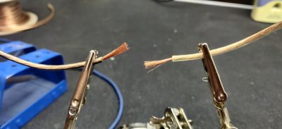
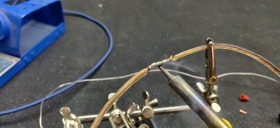
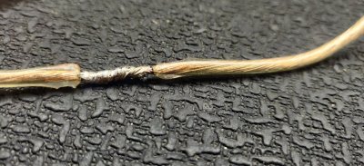
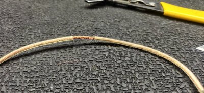
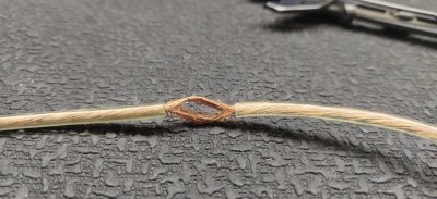
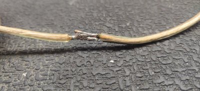
with a lot more people working on their trucks and adding lights, relays, switches, etc i figured i should post how i think is the proper way to make a connection. there are a few different ways to make an electrical connection and i will go over some of them. first up is soldering. now this is a controversal type of connection because its very easy to improperly solder wires together. this first pic is how i see many people solder. they tin both sides of the wires and then melt the solder between the two wires while the wires are touching. i purposely half assed the job because this is a typical type of solder connection i see when this is done this way. as seen in pic #2. a lot of times people will try to solder and since they are connected, think it will hold. however just having the solder as the "mortar" holding these two wires together, is not a solid connection and the solder can break causing the wires to seperate.
IMG_20201224_130127.jpg

IMG_20201224_130451.jpg
 
OP
OP
The Car Stereo Company

The Car Stereo Company

aka grumpy car stereo guy
Supporting Member
Joined
Jul 8, 2012
Posts
31,738
Reaction score
21,757
Location
here, on frf
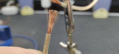
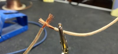
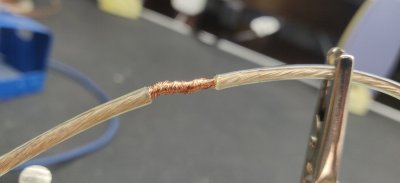
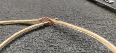
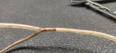
now im going to show you how i solder. it makes for a much better connection and much less risk of having a bad solder joint. first up, i stip back a little more wire. this is about 1/2 or 5/8 in. then i flare out the wires as seen in the second pic. i intertwine the wires (pic#3) then twist them togetherwith the ends of the wires on each end, effectivley making a barrel. then solder the wires allowing for enough solder to absorb into the wire

IMG_20201224_130621.jpg

IMG_20201224_130756.jpg

IMG_20201224_130831.jpg

IMG_20201224_130857.jpg

IMG_20201224_130950.jpg
 
OP
OP
The Car Stereo Company

The Car Stereo Company

aka grumpy car stereo guy
Supporting Member
Joined
Jul 8, 2012
Posts
31,738
Reaction score
21,757
Location
here, on frf
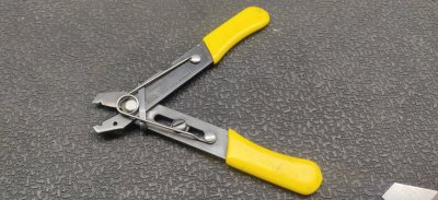
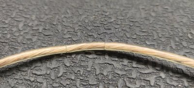
when connecting to a wire in the truck with solder and you dont want to cut the wire this is how i do it. first need the right tool. these wire cutters/strippers have an adjustable nut which allows you to cut the insulation without cutting the wire. i cut the insualtion about 3/4 in apart from each other. then i use a razor blade to cut the insulation out inbetween. next i take the tip of the blade and seperate the wire strands in half. i will take whatever wire im adding and feed it through the opening i just made

IMG_20201224_134703.jpg

IMG_20201224_134714.jpg

IMG_20201224_134808.jpg

IMG_20201224_134844.jpg

IMG_20201224_134923.jpg
 
Last edited:
OP
OP
The Car Stereo Company

The Car Stereo Company

aka grumpy car stereo guy
Supporting Member
Joined
Jul 8, 2012
Posts
31,738
Reaction score
21,757
Location
here, on frf
continued.... can only upload a few pics at a time.....

next up i twist the wires together again and solder just like i would normally. then you can insulate however you want. typically with this, since you cant add heat shrink, i use liquid electrical tape and then once dry, go over a second coat and then use the tessa tape designed for outside. (not the cloth tessa tape)

IMG_20201224_134943.jpg
 
OP
OP
The Car Stereo Company

The Car Stereo Company

aka grumpy car stereo guy
Supporting Member
Joined
Jul 8, 2012
Posts
31,738
Reaction score
21,757
Location
here, on frf
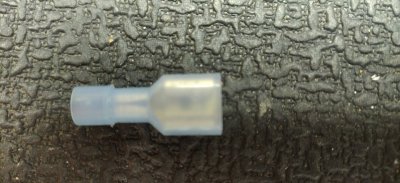
butt connectors/spade/bullet connectors

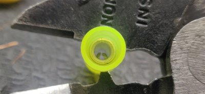
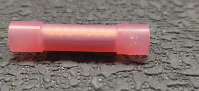
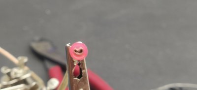
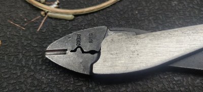
the biggest issue with these connectors is where you crimp them. if you look at any wire end on any vehicle, you will see a crimp type connector, however not butt connectors but its a crimp style none the less. so using butt connectors will work fine, but it needs to be done the right way. first up is a standard butt connector. i used the yellow so its easier to see. what people dont realize is that most of these have a seam down the length of it and if improperly crimped, will split the seam and the wire will fall out. you can kind of see the seam on the red one if you zoom in. so what happens is the seam splits as you can see in the pic. i use a set of klein crimpers and if you look it has the toooth on one side. i always put that tooth opposite of the seam of the butt connector. pic #1 shows what im talking about

IMG_20201224_132039.jpg

IMG_20201224_131222.jpg

IMG_20201224_131506.jpg

IMG_20201224_131305.jpg
 
OP
OP
The Car Stereo Company

The Car Stereo Company

aka grumpy car stereo guy
Supporting Member
Joined
Jul 8, 2012
Posts
31,738
Reaction score
21,757
Location
here, on frf
the best way to avoid having a bad connection with a butt connector is to buy seamless ones, but not everyone knows this.

marine butt connectors....
IMG_20201224_132738.jpg
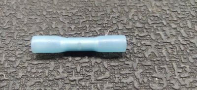
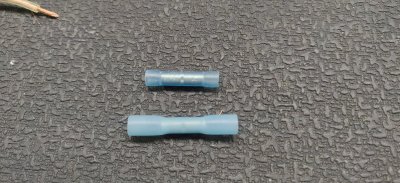
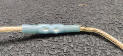
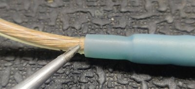
they are the same as a normal butt connector, but have heat shrink and gel that activate when heated.

IMG_20201224_132805.jpg
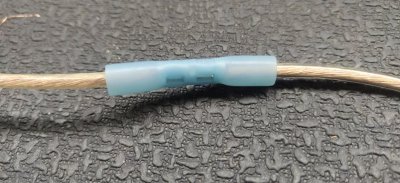
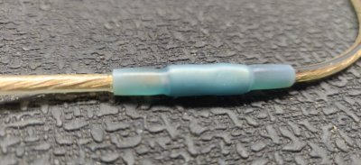
after making the crimp connections heat it with a heat gun to shrink the insulation. now there is one downfall to this and that is the a lot of times the insulation will break at the crimp point so you may have to tape the holes

IMG_20201224_132949.jpg

IMG_20201224_133107.jpg

IMG_20201224_133130.jpg
 
Last edited:
OP
OP
The Car Stereo Company

The Car Stereo Company

aka grumpy car stereo guy
Supporting Member
Joined
Jul 8, 2012
Posts
31,738
Reaction score
21,757
Location
here, on frf
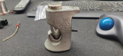
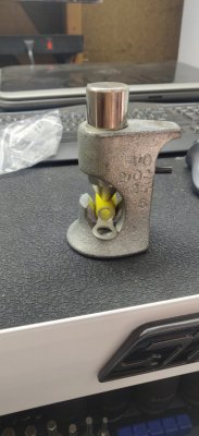
4ga and larger ring terminals can be fun. if you dont have this
IMG_20201224_133850.jpg IMG_20201224_133930.jpg
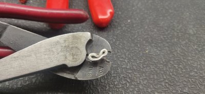
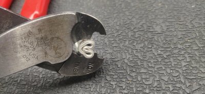
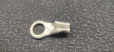
then you arent out of luck. you can use your handy klein crimpers, or equivelent. first step is to crimp it down then i crimp it sideways

IMG_20201224_132309.jpg

IMG_20201224_132346.jpg
this has worked for me very well . you just need to make sure you get a lot of force on it

IMG_20201224_132355.jpg
 
OP
OP
The Car Stereo Company

The Car Stereo Company

aka grumpy car stereo guy
Supporting Member
Joined
Jul 8, 2012
Posts
31,738
Reaction score
21,757
Location
here, on frf
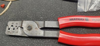
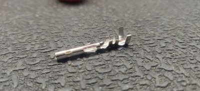
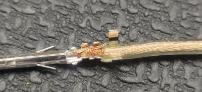
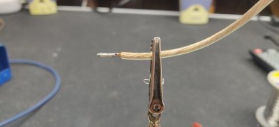
molex/duetche connectors. once again need the right crimper for the job. IMG_20201224_132722.jpg same as a crimp connecrion, strip back enough wire to fit the pin IMG_20201224_132722.jpg IMG_20201224_132421.jpg IMG_20201224_132421.jpg IMG_20201224_132506.jpg the last set of prongs need to go into the insulation of the wire. the smaller prongs go into the wire itself. as thats what hold the connection together
 
Top