Automatic Tailgate lock

Disclaimer: Links on this page pointing to Amazon, eBay and other sites may include affiliate code. If you click them and make a purchase, we may earn a small commission.

OP
OP
MTF

MTF

FRF Addict
Joined
Nov 27, 2010
Posts
5,358
Reaction score
2,284
Location
Celebration, Florida
The design engineer is looking into it.

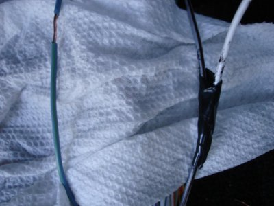
In the meantime does anybody know what the color codes are of the wires coming from the door lock selenoids inside the doors.
These are the wires we need to hook up to.

Or does anybody know how easy the door panels come off without destroying them?

I watched the guy on Youtube take the door panel off a F-150 and I will not try that unless I have no choice.

I can not beleive that it's this hard to search for the color codes at the door lock selenoid.

I found this at an alarm website I guess I'll have to see if that's easy access.

WIRE
spacer.gif
COLOR
spacer.gif
POLARITY
spacer.gif
LOCATION
spacer.gif


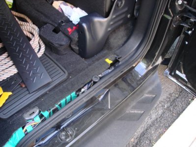
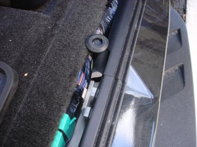
Power Unlock PINK/GREEN (-) AT BCM MODULE BEHIND TRIM IN REAR OF CAB ON DRIVERS SIDE PIN #1

PowerLock PINK/YELLOW (-) AT BCM MODULE BEHIND TRIM IN REAR OF CAB ON DRIVERS SIDE PIN #9


Also found this at

http://www.svtoffroad.com/f76/wire-colors-power-door-locks-2602/

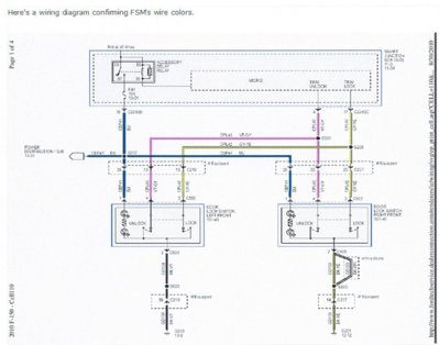
This is what a Ford Service Tech would see on Fords server.
I know it's hard to see. I copied as a PDF but it's too big the paste so I printed it and scaned it as a picture.
Just go to the link


I may also try this:

I have a 2010 Harley Davidson Edition and just installed a DynoLock and have a wiring question. The directions which came with the kit are completely wrong as far as which wires to tap into. I searched the site and found a nice thread with pics from Deano-FX4 but still have a question. Using the grey/brown "lock" wire works and using the light blue/light green "unlock" works but the tailgate unlocks with the first push of the unlock button. I would like to have the tailgate unlock with the rear doors (or when the unlock button is pressed twice). Does anyone else have any more information on this matter?
 

Attachments

  • 2010 F-150 Wiring.jpg
    2010 F-150 Wiring.jpg
    96 KB · Views: 171
Last edited:
OP
OP
MTF

MTF

FRF Addict
Joined
Nov 27, 2010
Posts
5,358
Reaction score
2,284
Location
Celebration, Florida
Wires are found go to this thread on this forum!!!!!!!!!!!!!!!!!!!!!!!

http://www.fordraptorforum.com/f52/automatic-tailgate-lock-3878/

I am sitting in my crane here in New York waiting to go home early and what happens a freaking earth quake
now they shut the job down, still waiting to do the last few picks.
It's gonna get too late for me to try it tonight :banghead::banghead::banghead::banghead:
 
Last edited:

DubbsFaris

Full Access Member
Joined
Apr 11, 2011
Posts
886
Reaction score
378
Location
Alamo
No problem,

Life happens, and it will be there for you to do when you have the time! Im watching closely!
 
OP
OP
MTF

MTF

FRF Addict
Joined
Nov 27, 2010
Posts
5,358
Reaction score
2,284
Location
Celebration, Florida
WELL I JUMP THE GUN

I going crazy now

I,m sitting in my truck now and found the wires, but they do not work and the Gy/Bn is connected to the white wire to the alarm.

It worked for the 2010 Harley Davidson Edition!
Unless he did not actually hook up the wires and just did a voltage test.
He would have the same problem as us.

Pop and lock did say that the Manufactures like to change the wires from year to year and trim to trim.

I tried to take the door panel off and stick my camera in there but I could not lift it up high enough to unhook without removing the door release handle. I watched the guy on youtube but he was not to clear on how to use that special tool.

Maybe Mr Doubleeaz can whip in that DVD and see if he can find something else.

If I have off tomorrow I am going the call SVT and try to get to the bottom of this issue!!!!!!!
And Call 1 800 Fordkey and get me to Audiovox (makers of the Ford alarms), they know were to tie into.
I had to call them before for my Pace Edwards Electric Remote Control Bed Locker to work with my Ford Gold Alarm
6 button key fob.
They might have different schematics then the Ford Service Manual DVD.


The only other option is get into the door or get into the panel on the drivers side rear cab panel, that looks like you have to remove the seat back and look at the BCM and maybe finding these pink wires.

In the mean time I found something else useful In the channel where the wires are,
I found a hole with a blank grommet in it towards the rear fo the cab.
Instead of running the wires through the firewall just make a little hole and run the wires through the center of the grommet and then fill with silicone.
I will paste Pictures.
 

Attachments

  • DSC00005.jpg
    DSC00005.jpg
    86.1 KB · Views: 117
  • DSC00003.jpg
    DSC00003.jpg
    96.7 KB · Views: 106
  • DSC00001.jpg
    DSC00001.jpg
    95.7 KB · Views: 105
Last edited:

gordhunt

Full Access Member
Joined
May 31, 2011
Posts
715
Reaction score
112
Thanks man havent had time to work on mine cant believe its so tough to get that info
 

Doubleeaz

Active Member
Joined
Mar 4, 2011
Posts
50
Reaction score
2
I looked in more detail at the wiring diagram. At the Smart Junction Box (SJB), the GY-BN wire from one side of the solenoid is labeled door lock all. The BU-GN wire is labeled driver unlock. There is a VT-GY wire from the passenger door labeled passenger door unlock. What I think this means is that the door solenoid is grounded through the case. A 12V signal on the GY-BN wire will lock all doors. A 12V signal on the BU-GN wire will unlock the drivers door. The wiring diagrams also show that the relays that control the solenoids are not serviceable meaning they are inside the SJB.

If this is correct, and the pop-n-lock solenoid requires that 12V and ground be applied in one direction to open and the opposite direction to close, we will not be able to wire directly from the pop-n-lock solenoid to the existing wires.

We will need to create a circuit that will only apply 12V and ground to the pop-n-lock solenoid if 12V is present on either GY-BN or BU-GN wires. If not, the pop-n-lock solenoid should not have any voltage applied. Leaving voltage on this solenoid too long will burn it out.

If anyone has a good idea, please chime in. Otherwise it is going to take me a couple days to figure something out as I am attending a conference right now.
 

Doubleeaz

Active Member
Joined
Mar 4, 2011
Posts
50
Reaction score
2
What we are going to need is an h-bridge for the pop-n-lock solenoid. A h-bridge is used to reverse the polarity of voltage across the terminals of a motor or solenoid. This is unfortunately going to require 4 relays or other devices. You can do a search on google for h-bridge but essentially what you are doing is having a relay on each terminal of the pop-n-lock solenoid that connects to 12V and ground. You connect the control signal from a 12V relay on one side (A) and a ground relay on the other side (B) to the control signal to lock from the Ford wiring harness. You connect the control signals from the 12V relay on B side and the ground relay on the A side to the control signal for unlock in the Ford wiring system.

Need to do a search to see if anyone makes a h-bridge relay pack or similar device that handles 12V and whatever we think the current rating of the pop-n-lock solenoid is.
 
OP
OP
MTF

MTF

FRF Addict
Joined
Nov 27, 2010
Posts
5,358
Reaction score
2,284
Location
Celebration, Florida
I had mention this before a couple of posts back

Commandoalarms.com would have these items

Door Lock Relay Module for 5 Wire Reverse Polarity Door Locks

or

Commando Universal 2 Door Power Lock Kit

or

actuatorrevpol.gif


You did also mention that the wires coming from the selenoid is a two wiring revesable setup.

You also stated that The wiring diagrams also show that the relays that control the solenoids are not serviceable
meaning they are inside the SJB.

That is why I am asking about the two wires from the (actuator, aka. Motor) we need to tie directly to them!

Commandoalarm.com did point out that there is a difference between Selenoid and Actuator

Do think maybe SVT got CUTE and changed the wires around?

Question, where is this Smart Junction Box (SJB) located or is that refering to the BCM.


Just got off the phone with Commando they are willing to help us, sending thread link now.

Crossing my fingers!!!!!!!!!!


I found wiring codes for a 2011 Ford explorer XLT and all Ford Trucks and SUVs after looking at about dozen different Models.

http://www.the12volt.com/installbay/vehiclewiring/1/yeard/Ford.html

Power Lock blue/green - driver kick or BCM, black 26 pin plug (C), pin 6
The BCM (Body Control Module) is the dash fuse box, under the driver dash.

Power Unlock yellow/purple - driver kick or BCM, black 26 pin plug (C), pin 8
The BCM (Body Control Module) is the dash fuse box, under the driver dash.

Lock Motor gray/brown 5 wire driver kick, door harness

Driver Unlock Motor blue/green 5 wire driver kick, door harness

Passenger Unlock Motor purple/gray 5 wire driver kick, harness to rear


It's pouring rain outside right now but I'll give these wires shot.

blue/green
yellow/purple
 
Last edited:
OP
OP
MTF

MTF

FRF Addict
Joined
Nov 27, 2010
Posts
5,358
Reaction score
2,284
Location
Celebration, Florida
Juat waiting for a break in the rain I want to try those wires before IRENE gets here!
I have a big two car garage but the Raptor is to tall to fit in.
OK nobody get cute and say "let the air out of the tires." I thought about that already.
I would have to let all the air out and risk breaking the tire pressure sensors.
That reminds me I have to run another report from the truck.
 
Last edited:
Top