
spack
Member
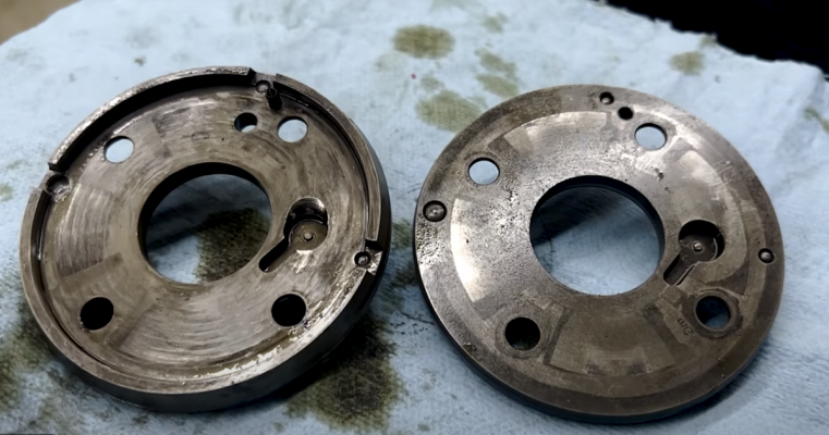
There has been a lot of phaser posts on this forum. Mostly those have been about warranty work. This post is about what I wanted to know and couldn’t find. It’s not about when to advance and retard. It’s about how Ford brings those actions about. Theory can be found in other places not related to ford. My questions were more about how Ford’s phaser are constructed, how they are initialized, what forscan tells us relative to that, how and why phasers break, and what the solutions might be. So I bought some used MLZ… and H3LZ…-CD parts, opened them up.
The basics:
Cam phasers alter the position of the camshafts relative to the crankshaft and thus when intake and exhaust valves open and close relative to the piston positions. Without phasers this relationship is fixed, which is how things used to be. Ever seen and heard a 1960s muscle car idle? Its camshafts and ignition timing had idle as an after thought. We were happy it at least kept idling until we stuck our foot into it. Then that engine got happier and smoother and more powerful. The cam’s fixed timing was aimed at horsepower to the exclusion of civilized behaviour. Phasers help an engine work at both ends of the spectrum. Phasers alter when fuel/air starts and stops entering on intake, and when exhaust starts and stops exiting on the exhaust cycle. Changes to the camshaft’s position relative to the crankshaft wouldn’t be necessary except for a couple of qualities of air. It’s springy (compressible), and it has mass. Basically it resists movement when stopped and once moving, it resists stopping. And these characteristics change based on temperature and pressure. Even if the characteristic of air didn’t change, as engine RPM increases, the time air takes to enter and exit the combustion chamber is more or less bounded. But the time allowed for entry and exit gets smaller with higher engine speed. Delay of air movement becomes a bigger percentage of the engine cycle at speed. Throw in a turbo charger, and you have another variable that influences how the air moves and how long it takes. Change exhaust headers, and the exhaust exit time changes. There becomes a nearly infinite set of timings for optimum performance. And one persons performance may be a California dude’s pollutant. The cam phaser is one very limited way of dynamic tuning to achieve some set of performance goals. I say limited because there are many more things we could do with valves than decide when they open and close; how far they open for example. And with a phaser, if you open a valve sooner, you also close it sooner. What if we wanted to open it sooner and close it later (duration). Can’t do that with a phaser. But a phaser is an amazingly simple device that allows the camshaft relationship to the crank to be controlled. Unlike air, oil is not compressible. The cam phasers used on most modern cars use oil pressure to turn the camshaft back and forth, through a limited range, inside the camshaft sprockets. By pushing oil into one chamber (or set of chambers) in the sprocket, the camshaft itself can be pushed ahead (advanced) past its current position relative to the sprocket and thus crankshaft. By pushing oil into an opposing chamber we can push the camshaft behind (retard) its current position. If no oil is allowed in or out, the camshaft stays glued to the sprocket. And that’s all there is to the basic device. A couple of oil ports in and an exit or drain port out. Oh and there is a locking pin, sigh…. To take care of startup when there is no oil pressure.
The control system is detailed in the following drawing.

At its core is a PID, which stands for Proportional Integral Derivative controller. The PID represent closed loop control. Its purpose in life is to keep its 2 inputs as close together as possible. One input, the desired camshaft angle, which is the SetPoint(SP) in PID lingo, comes from software which uses all sorts of other inputs to decide what the cam angle ought to be. The other input, the actual camshaft angle, which is the Process Variable (PV) in PID lingo, comes from a position sensor on the camshaft. The PID assures that whatever the software wants, the software gets. PIDs are everywhere in car control. Cruise control is PID controlled. The Setpoint being what you set the road speed to, and the ProcessVariable, coming from the same sensor that drives the speedometer. The output of the PID drives the accelerator pedal. If you encounter a hill and the car starts to slow, the PID output increases, producing more engine power, until the speed increases. In the camshaft case the output of the PID is converted into a pulsed output, which drives a field effect transistor, which drives a solenoid, which drives a spool valve, which drives oil into and out of the cam phaser, which drives the cam’s position relative to cam sprocket, and ultimately relative to the pistons position. A bit more on that later.
So here we go with more Ford specific stuff….
On start up and idle…
The Exhaust Phaser’s default lock position is fully advanced.
The Intake Phaser’s default lock position is fully retarded.
Why those are the default positions is not the focus of this post. That’s what they chose.
From a control point of view, the above has implications as follows. By arbitrary definition, advancing camshaft timing is always decrementing in degrees and retarding is always incrementing, for both exhaust and intake cams. Again arbitrarily, 0 degrees is always the lock position in both. So in the exhaust case the numbers will start from 0 degrees (locked) as the most advanced position and increment from there to retard. The numbers are never in the negative range. Intake also starts from 0 (locked) but as the most retarded position. From there the numbers go negative to infer more advance. The numbers are never positive. These are indeed arbitrary definitions but cam position will be reported this way by an ECU monitoring and configuration tool like Forscan. They are also the language the PIDs speak.
Solenoids are electrically actuated devices used to control the oil valves that influence oil flow to the chambers within the camshaft sprockets. Just like the lock pin position has implications to the positional definitions, these starting positions also have implication relative to the control solenoids and what the PWM duty cycles mean. PWM stands for pulse width modulation and refers to the electrical signal that the ECU feeds the solenoid to control it. It’s measured in percent and is another informative variable one can see with Forscan. At a minimum it tells us what the ECU and thus the PID is trying to tell the solenoid to do; like advance, retard, or hold steady. From a control standpoint, an unpowered solenoid should match the lock positions. An unpowered solenoid is by definition, 0% duty cycle. The phaser default lock positions imply that duty cycle means something different between exhaust and intake. 0 duty cycle means full advance for exhaust because that is where the exhaust phaser is in its default position. Incrementing duty cycle form there must mean to retard. Conversely, 0 duty cycle means full retard for intake. Increasing duty cycle from there must mean advance. This brings the locked positions into agreement with an unpowered ignition system about to start and it brings percent duty cycle in agreement with which direction exhaust and intake can go from their respective home positions with increasing duty cycle or increasing PID output.
A little bit more on Solenoids: Control of the oil into the advance and retard chambers of the phaser is controlled by selecting oil pressure to one side or the other through a spool valve. The spool valves turns linear shaft valve movement in or out, into selection of the phaser chamber to push oil into and allow oil out of. A solenoid creates the linear force into the valve, and a spring returns the valve when that spring overpowers the solenoid. The higher the duty cycle the greater the force. A solenoid is a variable force actuator, not a linear position actuator. Therefore a particular duty cycle does not imply an exact oil flow in either the advance or retard directions except at extremes or relative to something else. In fact the implementation of solenoid control will not be designed such that 100% duty cycle is legal. Another subject to be sure which has to do with the self inductance of electro-magnetic coils in solenoids. Not a topic that is important. So again, from a Forscan point of view, percent duty cycle is a magnitude reference but other than low duty cycles and high duty cycles, you can’t really infer advance, holding, or retard directly. You can determine, from looking at whether advance or retard angles are changing or not, as to what the holding duty cycle might be, and once that is known you can determine advance or retard intention and with what relative magnitude, by using the holding percentage as your reference. In other words, is the duty cycle above or below the holding reference and by how much?
The lock pin. At engine start, the lock pins hold the camshafts in their 0 degree, default positions; max advance for exhaust and max retard for intake. After startup, the ECU decides when to unlock them. Certainly after there is sufficient oil pressure to do so. How is the lock-pin unlocked given these starting points? The lock pin eject is a parasitic action in this architecture. Most car manufacturers who default lock at one extreme or the other, don’t have independent lock pin control and the complexity that might bring. Instead the architecture uses a method which is dependent on the starting position. With exhaust, since we start from the lock position as the most advanced position, it is the action of retarding oil pressure which will eject the pin. Thus there is a small oil channel from the retarding chamber that feeds the lock pin well. As the Solenoid receives its first command to retard, oil pressure which is meant to cause retarding action also pushes the lockpin out of the well. With intake, since we start from the lock position as the most retarded position, it is the action of advancing oil pressure which will eject the pin. Thus there is a small oil channel from the advancing chamber that feeds the lock pin well. As the Solenoid receives its first command to advance, oil pressure which is meant to cause advancing action also pushes the lockpin out of the well. In both cases there is a little bit of a battle going on between the pin going upward out of the well to unlock, and the advance or retard action creating a shear force on the pin and against the lock pin well, fighting the lock-pin’s upward movement out of the well. This is a source of wear on one side of the lock pin well; the side away from the default position. It is an architectural feature and quite frankly, a weakness. The telltale sign of this wear is a smoothly ramped well pin hole rather the a sharp cylindrical hole. Once sufficiently warn, the pin will no longer lock the cam and sprocket together. This is particularly apparent if the engine has been sitting long enough for oil to have drained out of the cam sprocket chambers. With no locking capability the camshaft bounces back and forth from one chamber limit to the other before oil pressure builds enough to allow PID control of cam position.
I’m including the following Forscan capture. It begins with engine start and there is some full acceleration and engine breaking included. I’m only looking at bank 1 exhaust and intake (bank 2 will be very much the same) in the following signal order. The first signal tells us if the ECU is doing closed loop control or not. Meaning the actual cam position is being used to achieve closed loop PID control. From there the signal order is: exhaust-duty-cycle, exhaust-desired-position, exhaust-actual-position. The next three are the same for intake. The last 3 signals are accelerator position, oil pressure, and RPM. There are a few things of interest.
.png")
The exhaust and intake positional ranges are as stated above. Exhaust position is only positive and intake position is only negative. The PWM duty cycles mean different things, to exhaust and intake, also as stated above. Increasing duty cycle means increasing angle (retardation) for exhaust. Increasing duty cycle means decreasing angle (advance) for intake. So on exhaust when you see PWM duty cycle go up, you will see degrees of position go up. On intake, when you see PWM duty cycle go up, you will see degrees of position go down.
If we look at places where the cam angles are holding steady, we can tell what duty cycle causes that. In my case about 36.2% for exhaust and about 35.2% for intake. Those numbers become meaningful when we look at engine start and other places where the duty cycles are above or below that reference. Before the engine starts, while it’s cranking, the PWM numbers exceed those holding values. Are they high enough to unlock the lock pins? They are of the correct magnitude. We assume no because if you look at oil pressure, it’s 0 at startup. In fact, in a fully warmed up engine, if you do a Wide Open Throttle start, which will allow the engine to crank indefinitely without starting, the oil pressure stays at 0. That was a surprise to me. In any case, during cranking, the PWM duty cycle goes to 43% for exhaust. For exhaust that is a retardation force, thus pumping oil into the retardation chamber, then back to 0 duty cycle to fill the advance chamber against the 0 degree stop limit. For intake a similar duty cycle causes the opposite to happen. We go to 37.13 duty cycle for an advance pressure to fill the advance chamber. Then back to 0% to fill the retard chamber against the stop. At the end of this initialization we can assume the phasers are pressurized to some degree. We may be able to assume the lock pins are ejected in both of the increased duty cycles noted at start. But I don’t think it’s important at that point. None the less, I just ignored the fact that there is no oil pressure anyway during this time. So nothing happened with regard to chamber pressures or unlock. With regard to oil pressure, once started oil pressure is switched on to a high pressure. Then after a minute it is switched to just over 20psi. It stays low until RPM goes quite high at which point it makes a step to a higher value of about 55psi only for the length of time at high RPM. The oil pump is under ECU control and is a 2 mode, variable displacement pump. Low pressure mode operation is designed to maintain oil pressure between 20 to 30 psi at speeds from 1000 to 3000 rpm with low engine load and engine oil temperatures at normal operating conditions. High mode operation is at all other engine operating conditions.
Back to the phasers…
The phasers have bias springs. The springs bias the camshafts towards the advance direction. How those are calibrated I don’t know but probably against the aggregate force of driving the cams against the valve springs. The intent would be to make the oil pressure required to advance, similar to retard. There is an asymmetry in that they would help the exhaust cam head to the home position and pin lock on engine stop. But not for intake. This is probably immaterial. But the point is, they are not “parking springs”.
The difference between the MLZ and HL3Z…-CD parts…. There has been lots written about Ford’s cam phaser problems…. As though it’s a Ford issue. Try Googling CAM RATTLE followed by the car manufacturer of your choice. Toyota, Honda, Hyundai, the list goes on. You won’t come up empty. It has a lot to do with the fact that almost everyone has a phaser related to the same patent, and that patent is to do with the lock pin ejection method when using a vane and chambers phaser as discussed in this post. There is also information on this forum that says you need to have the MLZ parts to have permanently fixed the potential phaser issue. But I question that. Every picture I have seen of a failed HL3Z part is version -CC or earlier and the CD parts have an interesting change. Having said that, there are differences between the MLZ part and the HL3Z … -CD parts. They are NOT architecturally different. In other words, lock pin ejection is still linked to exhaust retard or intake advance and the force battle that architecture creates against the lock pin well sidewall. What is different comes down to 2 things, The MLZ part has more depth axially than the HL3Z parts which means the advance and retard chambers have more volume and create more advance or retarding torque in the MLZ parts given the same oil pressures. Although this is somewhat offset by the fact that the chamber diameter across is less than the HL3Z parts. The bias spring constant on the MLZ part is higher. The second difference is in how the lock pin well is fed with oil to eject. In the MLZ part, the channel that feeds the well is in the vane and not in the well plate. The well sits by itself with no channel directly connected to it. The effect of the differing designs is the same. Well oil from the appropriate adjacent chamber displaces the pin. There is an immaterial visual difference, There is a bias spring cover which is press fit on the MLZ parts. This serves to keep the bias spring in place because the studs the springs anchor to, don’t have capture heads like the HL3Z parts. It’s not possible to look at one phaser versus the other and conclusively state anything about which is better. I wouldn’t bet on either. The HL3Z -CD parts are distinctly different than their earlier counterparts in how the lock pin well is constructed. Previously the well did not have a sidewall where the oil channel fed it. Now it does. So presumably, less oil pressure will float the pin and the pin is more symmetrically supported when in the well. But the overall architecture between both phaser types is unchanged.
On the subject of the lock pin architecture, the following patent https://patents.google.com/patent/US20050188933A1/en refers to an improvement over prior-art and that prior-art is the Ford design and Toyota design and everybody else’s design. They claim the prior method is prone to trouble because of the shear force versus ejection force mentioned in this post. Their solution is to feed the lock pin well from both retard and advance chambers thus allowing the solenoid to dither and feed both wells at the same time to cause pin eject. This results in overall well pressure without advance or retard torque, leaving only the lock pin to experience ejection pressure. After unlock the phaser can be advanced or retarded, avoiding the shear force on the pin well. This patent is quite elucidating in that it appears to be well known in the industry that the prior-art has a very specific flaw that creates a problem just about every car manufacturer has seen to one degree or another. Yet the industry has been focused on making the prior-art work for longer, rather than addressing the root cause.
Open questions and actions:
Spool valves - Spool valves can have a mid position where all valves are closed which serves to not allow oil in or out of the phaser, serving as a hold position with no pin eject pressure…. Or… mid position can be both advance and retard chambers receiving a small amount of pressure which serves to hold position but also keeps pressure in both advance and retard chambers. This would serve to eject the lock pin without a shear force. What Does ford do?
There is a TSB called 21b10. The graphs shown have it applied. What is it really doing? There was an additional 21b10 supplement. How is it different and how do you tell what you have? Oil pressure still seems to be low under most operating conditions. There is one place in the graphs where a lock pin surely gets a lock command. Why? Operational locking seems like something worth avoiding.
Auto start/stop will definitely cause pin locking just like any engine stop. Will turning that off prolong lock pin well life? It would seem so.
WOT start to build oil pressure through prolonged cranking seems pointless given what was observed with oil pressure. More measurements to be taken with longer crank times.
Is the eject and shear force action the root cause of phaser lifetime? Or is it unintended locking. Further measurements might shed light on it. Either one might cause the asymmetric pin well ramping wear seen in failed parts. However, given the patent to fix this, it seems like the former. Has Ford really struggled with such a simple cause for most of a decade?
More to write up on Ford’s VVT theory of operation. What performance goals are served by what desired cam timings under what conditions?
The basics:
Cam phasers alter the position of the camshafts relative to the crankshaft and thus when intake and exhaust valves open and close relative to the piston positions. Without phasers this relationship is fixed, which is how things used to be. Ever seen and heard a 1960s muscle car idle? Its camshafts and ignition timing had idle as an after thought. We were happy it at least kept idling until we stuck our foot into it. Then that engine got happier and smoother and more powerful. The cam’s fixed timing was aimed at horsepower to the exclusion of civilized behaviour. Phasers help an engine work at both ends of the spectrum. Phasers alter when fuel/air starts and stops entering on intake, and when exhaust starts and stops exiting on the exhaust cycle. Changes to the camshaft’s position relative to the crankshaft wouldn’t be necessary except for a couple of qualities of air. It’s springy (compressible), and it has mass. Basically it resists movement when stopped and once moving, it resists stopping. And these characteristics change based on temperature and pressure. Even if the characteristic of air didn’t change, as engine RPM increases, the time air takes to enter and exit the combustion chamber is more or less bounded. But the time allowed for entry and exit gets smaller with higher engine speed. Delay of air movement becomes a bigger percentage of the engine cycle at speed. Throw in a turbo charger, and you have another variable that influences how the air moves and how long it takes. Change exhaust headers, and the exhaust exit time changes. There becomes a nearly infinite set of timings for optimum performance. And one persons performance may be a California dude’s pollutant. The cam phaser is one very limited way of dynamic tuning to achieve some set of performance goals. I say limited because there are many more things we could do with valves than decide when they open and close; how far they open for example. And with a phaser, if you open a valve sooner, you also close it sooner. What if we wanted to open it sooner and close it later (duration). Can’t do that with a phaser. But a phaser is an amazingly simple device that allows the camshaft relationship to the crank to be controlled. Unlike air, oil is not compressible. The cam phasers used on most modern cars use oil pressure to turn the camshaft back and forth, through a limited range, inside the camshaft sprockets. By pushing oil into one chamber (or set of chambers) in the sprocket, the camshaft itself can be pushed ahead (advanced) past its current position relative to the sprocket and thus crankshaft. By pushing oil into an opposing chamber we can push the camshaft behind (retard) its current position. If no oil is allowed in or out, the camshaft stays glued to the sprocket. And that’s all there is to the basic device. A couple of oil ports in and an exit or drain port out. Oh and there is a locking pin, sigh…. To take care of startup when there is no oil pressure.
The control system is detailed in the following drawing.
At its core is a PID, which stands for Proportional Integral Derivative controller. The PID represent closed loop control. Its purpose in life is to keep its 2 inputs as close together as possible. One input, the desired camshaft angle, which is the SetPoint(SP) in PID lingo, comes from software which uses all sorts of other inputs to decide what the cam angle ought to be. The other input, the actual camshaft angle, which is the Process Variable (PV) in PID lingo, comes from a position sensor on the camshaft. The PID assures that whatever the software wants, the software gets. PIDs are everywhere in car control. Cruise control is PID controlled. The Setpoint being what you set the road speed to, and the ProcessVariable, coming from the same sensor that drives the speedometer. The output of the PID drives the accelerator pedal. If you encounter a hill and the car starts to slow, the PID output increases, producing more engine power, until the speed increases. In the camshaft case the output of the PID is converted into a pulsed output, which drives a field effect transistor, which drives a solenoid, which drives a spool valve, which drives oil into and out of the cam phaser, which drives the cam’s position relative to cam sprocket, and ultimately relative to the pistons position. A bit more on that later.
So here we go with more Ford specific stuff….
On start up and idle…
The Exhaust Phaser’s default lock position is fully advanced.
The Intake Phaser’s default lock position is fully retarded.
Why those are the default positions is not the focus of this post. That’s what they chose.
From a control point of view, the above has implications as follows. By arbitrary definition, advancing camshaft timing is always decrementing in degrees and retarding is always incrementing, for both exhaust and intake cams. Again arbitrarily, 0 degrees is always the lock position in both. So in the exhaust case the numbers will start from 0 degrees (locked) as the most advanced position and increment from there to retard. The numbers are never in the negative range. Intake also starts from 0 (locked) but as the most retarded position. From there the numbers go negative to infer more advance. The numbers are never positive. These are indeed arbitrary definitions but cam position will be reported this way by an ECU monitoring and configuration tool like Forscan. They are also the language the PIDs speak.
Solenoids are electrically actuated devices used to control the oil valves that influence oil flow to the chambers within the camshaft sprockets. Just like the lock pin position has implications to the positional definitions, these starting positions also have implication relative to the control solenoids and what the PWM duty cycles mean. PWM stands for pulse width modulation and refers to the electrical signal that the ECU feeds the solenoid to control it. It’s measured in percent and is another informative variable one can see with Forscan. At a minimum it tells us what the ECU and thus the PID is trying to tell the solenoid to do; like advance, retard, or hold steady. From a control standpoint, an unpowered solenoid should match the lock positions. An unpowered solenoid is by definition, 0% duty cycle. The phaser default lock positions imply that duty cycle means something different between exhaust and intake. 0 duty cycle means full advance for exhaust because that is where the exhaust phaser is in its default position. Incrementing duty cycle form there must mean to retard. Conversely, 0 duty cycle means full retard for intake. Increasing duty cycle from there must mean advance. This brings the locked positions into agreement with an unpowered ignition system about to start and it brings percent duty cycle in agreement with which direction exhaust and intake can go from their respective home positions with increasing duty cycle or increasing PID output.
A little bit more on Solenoids: Control of the oil into the advance and retard chambers of the phaser is controlled by selecting oil pressure to one side or the other through a spool valve. The spool valves turns linear shaft valve movement in or out, into selection of the phaser chamber to push oil into and allow oil out of. A solenoid creates the linear force into the valve, and a spring returns the valve when that spring overpowers the solenoid. The higher the duty cycle the greater the force. A solenoid is a variable force actuator, not a linear position actuator. Therefore a particular duty cycle does not imply an exact oil flow in either the advance or retard directions except at extremes or relative to something else. In fact the implementation of solenoid control will not be designed such that 100% duty cycle is legal. Another subject to be sure which has to do with the self inductance of electro-magnetic coils in solenoids. Not a topic that is important. So again, from a Forscan point of view, percent duty cycle is a magnitude reference but other than low duty cycles and high duty cycles, you can’t really infer advance, holding, or retard directly. You can determine, from looking at whether advance or retard angles are changing or not, as to what the holding duty cycle might be, and once that is known you can determine advance or retard intention and with what relative magnitude, by using the holding percentage as your reference. In other words, is the duty cycle above or below the holding reference and by how much?
The lock pin. At engine start, the lock pins hold the camshafts in their 0 degree, default positions; max advance for exhaust and max retard for intake. After startup, the ECU decides when to unlock them. Certainly after there is sufficient oil pressure to do so. How is the lock-pin unlocked given these starting points? The lock pin eject is a parasitic action in this architecture. Most car manufacturers who default lock at one extreme or the other, don’t have independent lock pin control and the complexity that might bring. Instead the architecture uses a method which is dependent on the starting position. With exhaust, since we start from the lock position as the most advanced position, it is the action of retarding oil pressure which will eject the pin. Thus there is a small oil channel from the retarding chamber that feeds the lock pin well. As the Solenoid receives its first command to retard, oil pressure which is meant to cause retarding action also pushes the lockpin out of the well. With intake, since we start from the lock position as the most retarded position, it is the action of advancing oil pressure which will eject the pin. Thus there is a small oil channel from the advancing chamber that feeds the lock pin well. As the Solenoid receives its first command to advance, oil pressure which is meant to cause advancing action also pushes the lockpin out of the well. In both cases there is a little bit of a battle going on between the pin going upward out of the well to unlock, and the advance or retard action creating a shear force on the pin and against the lock pin well, fighting the lock-pin’s upward movement out of the well. This is a source of wear on one side of the lock pin well; the side away from the default position. It is an architectural feature and quite frankly, a weakness. The telltale sign of this wear is a smoothly ramped well pin hole rather the a sharp cylindrical hole. Once sufficiently warn, the pin will no longer lock the cam and sprocket together. This is particularly apparent if the engine has been sitting long enough for oil to have drained out of the cam sprocket chambers. With no locking capability the camshaft bounces back and forth from one chamber limit to the other before oil pressure builds enough to allow PID control of cam position.
I’m including the following Forscan capture. It begins with engine start and there is some full acceleration and engine breaking included. I’m only looking at bank 1 exhaust and intake (bank 2 will be very much the same) in the following signal order. The first signal tells us if the ECU is doing closed loop control or not. Meaning the actual cam position is being used to achieve closed loop PID control. From there the signal order is: exhaust-duty-cycle, exhaust-desired-position, exhaust-actual-position. The next three are the same for intake. The last 3 signals are accelerator position, oil pressure, and RPM. There are a few things of interest.
The exhaust and intake positional ranges are as stated above. Exhaust position is only positive and intake position is only negative. The PWM duty cycles mean different things, to exhaust and intake, also as stated above. Increasing duty cycle means increasing angle (retardation) for exhaust. Increasing duty cycle means decreasing angle (advance) for intake. So on exhaust when you see PWM duty cycle go up, you will see degrees of position go up. On intake, when you see PWM duty cycle go up, you will see degrees of position go down.
If we look at places where the cam angles are holding steady, we can tell what duty cycle causes that. In my case about 36.2% for exhaust and about 35.2% for intake. Those numbers become meaningful when we look at engine start and other places where the duty cycles are above or below that reference. Before the engine starts, while it’s cranking, the PWM numbers exceed those holding values. Are they high enough to unlock the lock pins? They are of the correct magnitude. We assume no because if you look at oil pressure, it’s 0 at startup. In fact, in a fully warmed up engine, if you do a Wide Open Throttle start, which will allow the engine to crank indefinitely without starting, the oil pressure stays at 0. That was a surprise to me. In any case, during cranking, the PWM duty cycle goes to 43% for exhaust. For exhaust that is a retardation force, thus pumping oil into the retardation chamber, then back to 0 duty cycle to fill the advance chamber against the 0 degree stop limit. For intake a similar duty cycle causes the opposite to happen. We go to 37.13 duty cycle for an advance pressure to fill the advance chamber. Then back to 0% to fill the retard chamber against the stop. At the end of this initialization we can assume the phasers are pressurized to some degree. We may be able to assume the lock pins are ejected in both of the increased duty cycles noted at start. But I don’t think it’s important at that point. None the less, I just ignored the fact that there is no oil pressure anyway during this time. So nothing happened with regard to chamber pressures or unlock. With regard to oil pressure, once started oil pressure is switched on to a high pressure. Then after a minute it is switched to just over 20psi. It stays low until RPM goes quite high at which point it makes a step to a higher value of about 55psi only for the length of time at high RPM. The oil pump is under ECU control and is a 2 mode, variable displacement pump. Low pressure mode operation is designed to maintain oil pressure between 20 to 30 psi at speeds from 1000 to 3000 rpm with low engine load and engine oil temperatures at normal operating conditions. High mode operation is at all other engine operating conditions.
Back to the phasers…
The phasers have bias springs. The springs bias the camshafts towards the advance direction. How those are calibrated I don’t know but probably against the aggregate force of driving the cams against the valve springs. The intent would be to make the oil pressure required to advance, similar to retard. There is an asymmetry in that they would help the exhaust cam head to the home position and pin lock on engine stop. But not for intake. This is probably immaterial. But the point is, they are not “parking springs”.
The difference between the MLZ and HL3Z…-CD parts…. There has been lots written about Ford’s cam phaser problems…. As though it’s a Ford issue. Try Googling CAM RATTLE followed by the car manufacturer of your choice. Toyota, Honda, Hyundai, the list goes on. You won’t come up empty. It has a lot to do with the fact that almost everyone has a phaser related to the same patent, and that patent is to do with the lock pin ejection method when using a vane and chambers phaser as discussed in this post. There is also information on this forum that says you need to have the MLZ parts to have permanently fixed the potential phaser issue. But I question that. Every picture I have seen of a failed HL3Z part is version -CC or earlier and the CD parts have an interesting change. Having said that, there are differences between the MLZ part and the HL3Z … -CD parts. They are NOT architecturally different. In other words, lock pin ejection is still linked to exhaust retard or intake advance and the force battle that architecture creates against the lock pin well sidewall. What is different comes down to 2 things, The MLZ part has more depth axially than the HL3Z parts which means the advance and retard chambers have more volume and create more advance or retarding torque in the MLZ parts given the same oil pressures. Although this is somewhat offset by the fact that the chamber diameter across is less than the HL3Z parts. The bias spring constant on the MLZ part is higher. The second difference is in how the lock pin well is fed with oil to eject. In the MLZ part, the channel that feeds the well is in the vane and not in the well plate. The well sits by itself with no channel directly connected to it. The effect of the differing designs is the same. Well oil from the appropriate adjacent chamber displaces the pin. There is an immaterial visual difference, There is a bias spring cover which is press fit on the MLZ parts. This serves to keep the bias spring in place because the studs the springs anchor to, don’t have capture heads like the HL3Z parts. It’s not possible to look at one phaser versus the other and conclusively state anything about which is better. I wouldn’t bet on either. The HL3Z -CD parts are distinctly different than their earlier counterparts in how the lock pin well is constructed. Previously the well did not have a sidewall where the oil channel fed it. Now it does. So presumably, less oil pressure will float the pin and the pin is more symmetrically supported when in the well. But the overall architecture between both phaser types is unchanged.
On the subject of the lock pin architecture, the following patent https://patents.google.com/patent/US20050188933A1/en refers to an improvement over prior-art and that prior-art is the Ford design and Toyota design and everybody else’s design. They claim the prior method is prone to trouble because of the shear force versus ejection force mentioned in this post. Their solution is to feed the lock pin well from both retard and advance chambers thus allowing the solenoid to dither and feed both wells at the same time to cause pin eject. This results in overall well pressure without advance or retard torque, leaving only the lock pin to experience ejection pressure. After unlock the phaser can be advanced or retarded, avoiding the shear force on the pin well. This patent is quite elucidating in that it appears to be well known in the industry that the prior-art has a very specific flaw that creates a problem just about every car manufacturer has seen to one degree or another. Yet the industry has been focused on making the prior-art work for longer, rather than addressing the root cause.
Open questions and actions:
Spool valves - Spool valves can have a mid position where all valves are closed which serves to not allow oil in or out of the phaser, serving as a hold position with no pin eject pressure…. Or… mid position can be both advance and retard chambers receiving a small amount of pressure which serves to hold position but also keeps pressure in both advance and retard chambers. This would serve to eject the lock pin without a shear force. What Does ford do?
There is a TSB called 21b10. The graphs shown have it applied. What is it really doing? There was an additional 21b10 supplement. How is it different and how do you tell what you have? Oil pressure still seems to be low under most operating conditions. There is one place in the graphs where a lock pin surely gets a lock command. Why? Operational locking seems like something worth avoiding.
Auto start/stop will definitely cause pin locking just like any engine stop. Will turning that off prolong lock pin well life? It would seem so.
WOT start to build oil pressure through prolonged cranking seems pointless given what was observed with oil pressure. More measurements to be taken with longer crank times.
Is the eject and shear force action the root cause of phaser lifetime? Or is it unintended locking. Further measurements might shed light on it. Either one might cause the asymmetric pin well ramping wear seen in failed parts. However, given the patent to fix this, it seems like the former. Has Ford really struggled with such a simple cause for most of a decade?
More to write up on Ford’s VVT theory of operation. What performance goals are served by what desired cam timings under what conditions?
Last edited: