OK guys! Here is my review/install write-up. I'm going to revise my original post with better information.
Alright, almost completely done. I'm waiting on the switch to wire up the led spot lights! I'll break this down into segments as I did them.
---Wiring the new F-150 headlight switch---
This is extremely simple. The motorcraft pigtail comes with pieces of heat shrink in the package. The old headlight switch comes out by pressing tabs on the back of the switch. You can access it from the panel on the drivers side that connects to the drivers door and provides the air for the drivers side window defrost. Pull out on the panel from the air duct and it comes right out very easily. Once you remove old headlight switch, pull the stock headlight pigtail out of the side panel. Cut one wire at a time and use the left air vent to hold the pigtail while you solder each wire. Don't forget to heat shrink it! You will have one left over wire on the bottom and the last 2 wires on the far right side of the pigtail are to send a ground signal to the relay, and another to receive a feed from the output on the relay to turn the little light on when the fogs are turned on by pulling the knob.
---Mounting the Duallies---
This part is simple and straight forward. The mounts you bought from rigid industries to attach the 2 pairs of duallys to the truck come with an instruction manual. 8 holes drilled later, you are good to go. Just replace the self tapping screws for the 4 holes closer to the center of the truck with grade 8 nuts and bolts. I don't trust self tapping screws. This is easy with a combination wrench and some painters tape. Just use the tape to hold the bolt on the end and insert it into the support beam. (Don't forget to maneuver two washers and two lock washers in there as well.
---Wiring the Relay---
On the relay, I decided to wire it by doing a constant switch rather than using the parking lights. This is because I have an aftermarket alarm and it won't activate the parking lights in automatic headlight mode. The switch has to be set to off. You can't pull the knob out to turn on the fog lights when the switch is set all the way to the left.
I went and found a wiring diagram for you guys to see.
Make sure you have a relay socket. It gives you the capability of swapping out relays if one goes bad much more easily.
Also, remember to build the relay harness off of the truck then install it once you have finished. I didn't provide exact measurements of each length of wire so make measurements for the lengths I didn't specify before starting to build the harness.
Also, remember to keep the 4 wires going into the cab marked so you can wire them properly.
I wired up the pins as follows -
Pin 30 & 86 :
Start by attaching a 6" piece of 16 gauge red primary wire to pin 30 on the relay. Cut a length of 16 gauge wire to reach to the positive terminal on your battery. Next, cut a piece of 16 gauge blue primary wire to 6" and attach it to pin 86 of your relay socket. Twist the two 6" wires and the long red length of 16 gauge primary wire you just cut together and solder, then heat shrink it. Next, attach an appropriate fuse holder and fuse inline of the wire running to your battery. Finish by soldering a ring terminal on the end to connect to your battery.
Pin 87:
Attach 3 pieces of red 16 gauge wire to pin 87, cut one to 12" long and two long enough to reach to the wire that activates the light on the headlight switch and also one side of the push button switch to turn the non road legal duallies off and on. Make sure the wire going to the push button switch and the wire going back to the rigid harness are kept separate from the two wires going to the headlight switch. You can make this easier by replacing one of the two red wires with a different color wire. This part is explained below
When you received your fog light mount kit from rigid, you should have received a harness that has 3 wires at the end that you will have to splice. This harness is the perfect length to reach to the relay which I mounted on the driver side of the engine bay, next to the relay box for the upfitter switches. The harness even has 4 Deutsch connectors that attach to the connectors on the back of the duallys.
The 3 wires coming out of the harness are one red positive, one blue positive, and one black ground. Solder and heat shrink the 12" red wire to the red wire coming off of the rigid harness. The next 2 wires coming off of pin 87 go to one side of your push button switch and another to the bottom right wire (if you are looking at the wire side of the Motorcraft pigtail you wired to the headlight switch earlier.)
Next, run another 16 gauge blue primary wire back to the blue wire coming off of the rigid harness. Connect it to the other side of your push button switch to turn the dually spots on/off.
Pin 85:
Unlike regular relay wiring, for this application, pin 85 is your trigger wire. The headlight switch sends a ground signal to this pin. But you will also need to run a ground wire to the negative coming off of the rigid wiring harness.
Attach 2 pieces of 16 gauge black primary wire to pin 85 of your relay socket. One 12" in length and another to reach the headlight switch pigtail. (You should now have 4 wires going to the inside of the cab.) Attach the 12" strand to the ground wire coming off of the rigid wiring harness.
---Wrapping the wiring harness---
Use electric conduit to wrap the individual wires. One small piece to cover the 4 wires going inside the cab and another to cover the several wires going to the rigid harness. The wire the comes off the of the push button switch will need to go to the rigid harness so make a U-shape in the wire at the relay plug and then out to the blue wire coming off of the rigid wiring harness. On my harness, I ran the wire going to the battery by twisting it around the rigid harness over to the far side Deutsch connectors of the rigid harness then behind the passenger headlight to the battery.
You should have 2 separate bundles coming off of the relay. We will call the one going into the cab the "switch bundle" and one going to the lights and battery "power bundle."
---Installing your harness---
"Power bundle"
1. Remove passenger side headlight.
2. Mount relay on driver side of engine bay.
3. Run the "power bundle along the driver side of the engine bay down behind the headlight and zip tie it in place. Be sure to pull the covering on the rigid harness back off of the Deutsch connectors and be sure the one with the red positive connects to the dot fog lights and the blue positive to the spots. Zip tie in place.
4. Run the remaining bit of the rigid harness to the passenger side duallies and repeat the connection process on step 3.
5. Run the positive wire with the ring terminal to your battery but remove the negative terminal on your battery first. Leave the negative disconnected until the end of the install.
The "power bundle" is done.
"Switch bundle"
1. Run your "switch bundle to the inside of the cab. I did this by removing the panel on the floor next to the seat then the panel around the parking brake release on the driver side. I then peeled back the carpet and pull up the piece of tape that covers a hole in the bottom of the cab. (Simply run the "switch bundle" down to the frame rail and to the hole in the bottom of the cab. Zip tie it in place)
2. The 4 wires going into the cab should have been kept separate by which switch they go to. One black, 2 reds and one blue.
a.Wire the black wire to the top right wire of the pigtail (if you are looking at the back of the switch.) This wire is your trigger wire for the relay.
b. Wire one of the positive wires coming off of pin 87 to the bottom right wire on the headlight pigtail. This is the wire that turns the little light on the switch on when the knob is pulled to turn the fog lights on.
c. Wire the other positive to one pin of your push button switch.
d. Wire the blue wire to the other pin of your push button switch.
Remember to solder and heat shrink these connections and wrap them with electrical tape or conduit. Zip tie the wires in place.
---Finishing up---
Use a 10mm wrench and remove the nut on the positive battery terminal then attach the positive ring terminal then reinstall the nut.
Attach negative terminal.
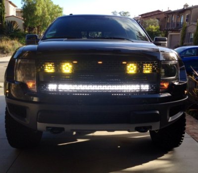
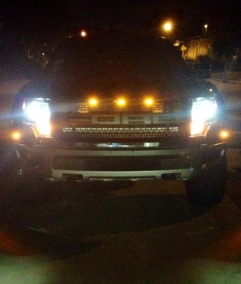
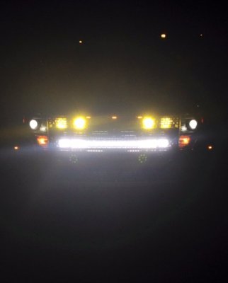
Enjoy your new lights! Remember to aim them properly. I aimed them on a flat surface 30' away from a wall.
Please PM me or comment if I missed something.