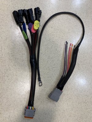
Inspired by some others I saw in this forum, I created this custom harness to make it simple and easy to add accessories to the upfitter switches.
The right side harness is the truck side. I will solder the 6 remaining wires to the 6 upfitter wires in the engine compartment. The long wire to the ring terminal goes to a 3/8" post that is a body ground on the top of the firewall near the access to the upfitter wires. This grounds all the ground wires on the 12-pin Deutsch connector. It's extended exactly 20 inches beyond the other wires to accommodate the extra length from the upfitter wires to the ground post (along a neatly hidden path that I measured with a spare piece of wire).
The left side harness is the accessory side. Any accessory I buy, I will solder a male 2-pin Deutsch connector onto it and plug it into the upfitter connection of my choice. In this way I can also easily change which upfitter has each accessory. It's as easy as taking the accessory's plug off the Aux 1 connection and plugging it back into the Aux 2 connection. For ease of future use, I put wire labels on each connector showing the Aux switch it corresponds to and its amp rating.
I also have a plan for the pass-through wires. I'll cover that when I get there.
I completely get that this level of wiring is unnecessary. I get that you can have the exact same result by butt splicing directly onto your upfitter wires. That's not why I did this. I enjoy creating custom wiring harnesses that could pass for factory equipment. It's a cathartic hobby for me.


