

GooseTuned says I need the JMS FuelMax to go any further with the truck and I noticed there was only one installation thread, and it was for crew cab trucks, so I figured I should add another.
My truck is a 2018 supercab with the following performance mods:
Fresh OEM long block with 1,500 miles
Garrett Powermax turbos
Full Race manifolds
Cobb dual intake
AMS inlet tubes
Full Race FMIC
Turbosmart BOV
Stainless Works 3" downpipes
SPD trombone resonator
Custom 4" dump exhaust
IDE 1050cc port injectors
Full Race radiator
Full Race transmission cooler
Radium Engineering catch cans
Cobb Accessport with GooseTuned tuning
Lots of other mods but those are the engine/performance items that matter. I'm running 100% E85 fuel 9 months of the year and 93 octane over the winter. After the addition of the Powermax turbos and manifolds, Goose said I had hit the limit of fuel flow and suggested the JMS. Let's get started.
The JMS Fuelmax piggybacks in between your fuel pump driver module (FPDM) and your fuel pump fuse to increase the voltage as the throttle pedal gets pushed down further. JMS recommends you locate the unit INSIDE the cab. You need to run a single wire to the throttle positions sensor underneath the driver's side footwell, and, you need to run the main harness out to the FPDM. One way or another, you'll need to route a wire from inside the cab to the outside of the cab.
The only other installation guide for this unit recommended unbolting the bed from the frame so the bed can be slid back enough to route the wiring through a factory grommet on the crew cab trucks. I was absolutely determined to avoid this at all cost given the number of bed bolts that break during disassembly, and because I have a bed cage that would have added at least a couple hours to this job. On Supercab trucks I am happy to report this is 100% NOT REQUIRED.


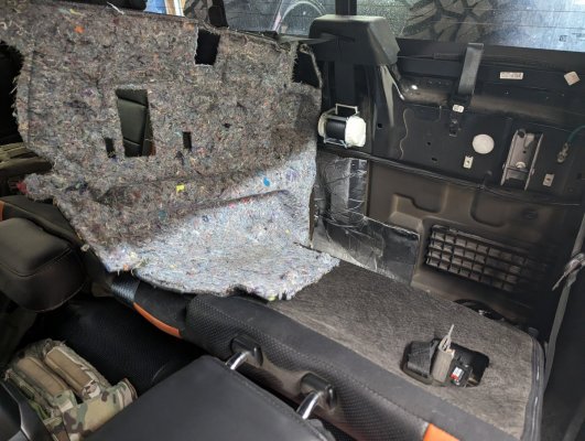
As you can see above, the FPDM is located on top of the crossmember toward the rear of the fuel tank, just to the left of the brake lines. There's a yellow tab you unlock and pull to the right first, which then allows the connector to pull free. The JMS harness plugs into the FPDM, into the OEM harness, and then gets routed up over the fuel tank where you'll connect it to the JMS unit once you get the harness fed down from the cabin area.
Simply connect the harness, and then feed the tail end up over the fuel tank and let it hang down for now. You'll want to leave the harness loose for now until everything is routed properly.


My truck is a 2018 supercab with the following performance mods:
Fresh OEM long block with 1,500 miles
Garrett Powermax turbos
Full Race manifolds
Cobb dual intake
AMS inlet tubes
Full Race FMIC
Turbosmart BOV
Stainless Works 3" downpipes
SPD trombone resonator
Custom 4" dump exhaust
IDE 1050cc port injectors
Full Race radiator
Full Race transmission cooler
Radium Engineering catch cans
Cobb Accessport with GooseTuned tuning
Lots of other mods but those are the engine/performance items that matter. I'm running 100% E85 fuel 9 months of the year and 93 octane over the winter. After the addition of the Powermax turbos and manifolds, Goose said I had hit the limit of fuel flow and suggested the JMS. Let's get started.
The JMS Fuelmax piggybacks in between your fuel pump driver module (FPDM) and your fuel pump fuse to increase the voltage as the throttle pedal gets pushed down further. JMS recommends you locate the unit INSIDE the cab. You need to run a single wire to the throttle positions sensor underneath the driver's side footwell, and, you need to run the main harness out to the FPDM. One way or another, you'll need to route a wire from inside the cab to the outside of the cab.
The only other installation guide for this unit recommended unbolting the bed from the frame so the bed can be slid back enough to route the wiring through a factory grommet on the crew cab trucks. I was absolutely determined to avoid this at all cost given the number of bed bolts that break during disassembly, and because I have a bed cage that would have added at least a couple hours to this job. On Supercab trucks I am happy to report this is 100% NOT REQUIRED.
As you can see above, the FPDM is located on top of the crossmember toward the rear of the fuel tank, just to the left of the brake lines. There's a yellow tab you unlock and pull to the right first, which then allows the connector to pull free. The JMS harness plugs into the FPDM, into the OEM harness, and then gets routed up over the fuel tank where you'll connect it to the JMS unit once you get the harness fed down from the cabin area.
Simply connect the harness, and then feed the tail end up over the fuel tank and let it hang down for now. You'll want to leave the harness loose for now until everything is routed properly.
Attachments
Last edited:


