Install Notes
Installed this charging system and grounding upgrade kit, looks very nice, included instructions with color pictures are good.
Here are some notes and pictures from my install experience and my DIY skill level which is average, took me about 3.5 hours with interruptions and picture taking. Comments in random order.
Wish the install instructions were posted on FRF GB listing, lots of good info to know before buying, and would have answered many questions. Especially if planning to upgrade the battery post terminals to ones that use bolted connections which tend to have 3/8" long bolt, that won't work with these lug end openings which are 1/4" to fit stock battery terminal connections.
1. Have bundle ties and high heat loom tape on hand.
2. Wish I had smaller diameter wire loom to replace the large diameter factory loom for cleaner look when re-installing alternator sensor wire. I only had electrical tape on hand to re-wrap wire loom, will replace later with smaller loom and high heat tape. Or, maybe high heat sheathing to match cable sheathing.
3. Cutting the fusible link wire is the point of no return, oh crap, what I have gotten myself into, haha!
4. You will have to a cut hole in end of fuse box lid and notch in plastic lip on underside of lid. Picture 4 and 5. Would be nice if kit included template to trace out where to cut the hole for the huge cable to fit. I used a Dremel tool to cut out opening, it took me several lid on and off cycles to get a good fit, it ain't perfect, i.e. skill level.
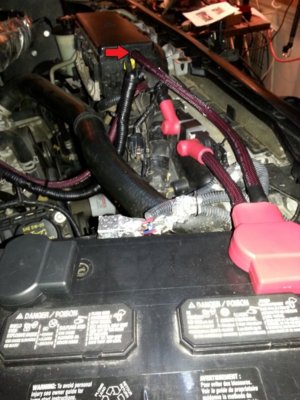
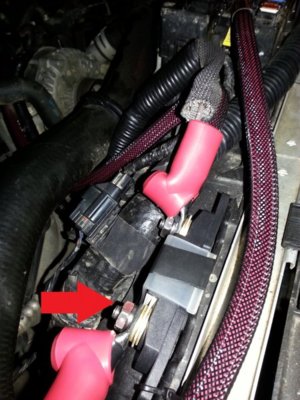
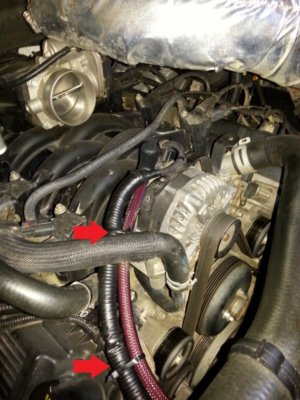
5. Very tight fitment for engine ground and negative ground cable connections. Picture 8, red arrows.
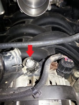
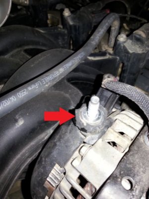
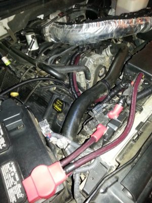
6. When you get to the step for removing the raised plastic lip around the alternator stud by using large screwdriver to pop this off, good luck, I couldn't figure out how to do this without busting the whole plastic cover on backside of alternator, i.e see skill level disclaimer above. I ended up breaking off the two plastic tabs as best alternative, since I was already past the point of no return. Dang, I hate breaking things! Picture 2 and 3.
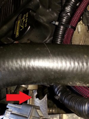
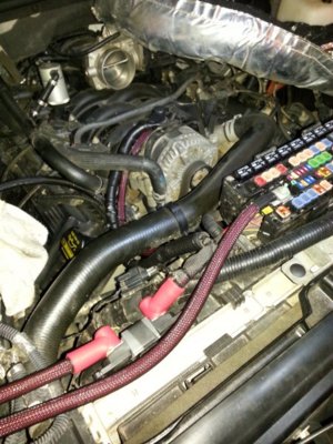
7. When trying to remove the plastic holder that holds the factory alternator cable/sensor wire bundle to tab on edge of radiator fan guard, the plastic broke, dang, third thing I F'd up. Keep going, there is no going back! Picture 1. Bundle ties to stock attachment points Picture 9.
8. Fuse block assembly, no directions on fuse/lug sequence, assume fuse goes in between two flat washers, then terminal end goes between top flat washer and lock washer, and then tighten nut. Picture 7. Personally, I wish the fuse post/fuse block had a cover that encased the entire assembly, it is too exposed to the elements in my opinion. My engine bay tends to become 100% coated in mud and stuff when off-roading, so, I'm gonna figure out a solution to totally encase and protect the fuse and posts.
9. I think the battery negative cable is about one inch too short, and I found it puts a twisting/binding force on negative battery terminal. This is a very tight fit and as this sheathed welding cable is very thick and not so flexible in short lengths.
10. Fuse block, wish there was one that had a pre-drilled screw/or threaded bolt hole in the bottom so you could attach to it through the factory attachment point(s) that held the plastic fusible link cover/assembly.
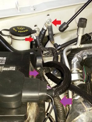
11. Next upgrade for me, because I want to get to military terminal setup, is to convert the negative/starter cable to a lug and in the process just remove the stock battery grounding cable, Picture 8 purple arrows, as to me, it's really not necessary now with this kit's monster cable and just makes for an overly tight fit. Just have to find a shop to properly install the lug. Same for positive terminal, there is a wire coming up underneath that is part of the stock terminal that I want to replace with a lug.
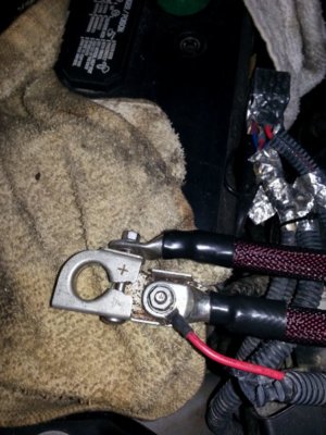
12. Picture 10 is of positive battery terminal setup.
Very nice kit. Picture 6.