Wiring a relay to upfitter switch

Disclaimer: Links on this page pointing to Amazon, eBay and other sites may include affiliate code. If you click them and make a purchase, we may earn a small commission.

soxfanjake

Member
Joined
Jan 21, 2015
Posts
8
Reaction score
15
Location
Nashville, TN
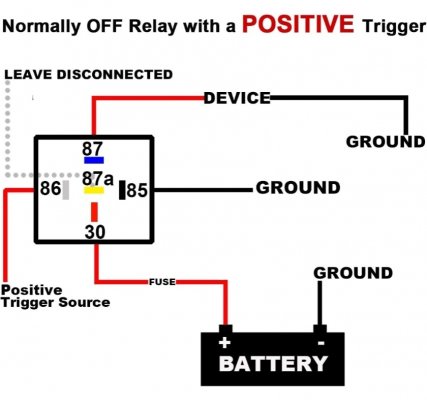
I'm installing a 12 volt outlet in the bed to power a Dometic Refrigerator/Freezer. I wired a standard 30/40 relay to the AUX 6 wire as shown in the "POSITIVE TRIGGER" pic. The 86 pin is wired to the AUX 6 wire as the trigger.

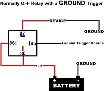
My problem is, the 87 pin is now hot when the AUX 6 switch is off, and dead when the AUX 6 switch is on. Obviously the opposite of what I was after. Should I be wiring as if it's a ground trigger like in the 2nd pic?

Thanks in advance for any help.
 

Attachments

  • Screenshot_20230906_194342_Amazon Shopping.jpg
    Screenshot_20230906_194342_Amazon Shopping.jpg
    119.1 KB · Views: 20
  • 5167BgdjJnL._AC_UF350,350_QL80_.jpg
    5167BgdjJnL._AC_UF350,350_QL80_.jpg
    10.7 KB · Views: 17

smurfslayer

Be vewwy, vewwy quiet. We’re hunting sasquatch77
Joined
Dec 16, 2016
Posts
16,300
Reaction score
24,045
try this relay diagram

30 is battery power
86 is ground/earth
85 is ‘trigger’ aka upfitter
87 goes to the accessory - in your case, the plug.

here’s another link that may explain it more eloquently than I:

"5 pin relays provide 2 pins (85 & 86) to control the coil and 3 pins (30, 87 & 87A) which switch power between two circuits. They have both normally open and normally closed connection pins. When the coil is activated, power will be switched from the normally closed pin to the normally open pin."
 
OP
OP
soxfanjake

soxfanjake

Member
Joined
Jan 21, 2015
Posts
8
Reaction score
15
Location
Nashville, TN
try this relay diagram

30 is battery power
86 is ground/earth
85 is ‘trigger’ aka upfitter
87 goes to the accessory - in your case, the plug.

here’s another link that may explain it more eloquently than I:

"5 pin relays provide 2 pins (85 & 86) to control the coil and 3 pins (30, 87 & 87A) which switch power between two circuits. They have both normally open and normally closed connection pins. When the coil is activated, power will be switched from the normally closed pin to the normally open pin."
Thanks so much for the reply. Sucks that neither diagram that came with my relays was correct (also sucks that I have to rely on diagrams because my electrical knowledge is so limited). Some cutting and re-heatshrinking in my future.
 

smurfslayer

Be vewwy, vewwy quiet. We’re hunting sasquatch77
Joined
Dec 16, 2016
Posts
16,300
Reaction score
24,045
he’s right, you only need a 4 pin. 5 pin can work, but you’ll have an unused post (needing to be insulated or tied/wrapped)
I understood you -had- a 5 pin.
 
OP
OP
soxfanjake

soxfanjake

Member
Joined
Jan 21, 2015
Posts
8
Reaction score
15
Location
Nashville, TN
he’s right, you only need a 4 pin. 5 pin can work, but you’ll have an unused post (needing to be insulated or tied/wrapped)
I understood you -had- a 5 pin.
Correct. I have a 5 pin only because I had a whole box of them. I'm just capping the middle pin.
 

downforce137

FRF Addict
Joined
Jan 5, 2016
Posts
1,910
Reaction score
2,525
Location
In Diana
its my understanding that the 5 pin relay makes the middle terminal hot when energized.. thats not what is happening here?

sounds like you have a normally on relay and when energized its hot on the middle pin, instead of 87

you need a normally off relay...
 
OP
OP
soxfanjake

soxfanjake

Member
Joined
Jan 21, 2015
Posts
8
Reaction score
15
Location
Nashville, TN
try this relay diagram

30 is battery power
86 is ground/earth
85 is ‘trigger’ aka upfitter
87 goes to the accessory - in your case, the plug.

here’s another link that may explain it more eloquently than I:

"5 pin relays provide 2 pins (85 & 86) to control the coil and 3 pins (30, 87 & 87A) which switch power between two circuits. They have both normally open and normally closed connection pins. When the coil is activated, power will be switched from the normally closed pin to the normally open pin."
Smurfslayer for the win! This is the correct wiring for this scenario. It's working now. Next stop, wiring the 5 & 6 switches to be hot with the engine off. Thanks for all the replies and help.
 

Attachments

  • Screenshot_20230909_153318_Chrome.jpg
    Screenshot_20230909_153318_Chrome.jpg
    145.6 KB · Views: 20
  • 20230909_153048.jpg
    20230909_153048.jpg
    288.4 KB · Views: 20
  • 20230909_153053.jpg
    20230909_153053.jpg
    410.3 KB · Views: 21

The Car Stereo Company

aka grumpy car stereo guy
Supporting Member
Joined
Jul 8, 2012
Posts
31,738
Reaction score
21,757
Location
here, on frf
its my understanding that the 5 pin relay makes the middle terminal hot when energized.. thats not what is happening here?

sounds like you have a normally on relay and when energized its hot on the middle pin, instead of 87

you need a normally off relay...
87 and 87a (middle pin) is a normally closed circuit. it is a complete circuit until the relay is powered. 87 and 30 is normally open. which means when the relay is powered they connect until power is off
 

Forum statistics

Threads
93,180
Posts
1,955,511
Members
56,460
Latest member
khunter
Top