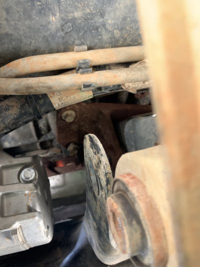
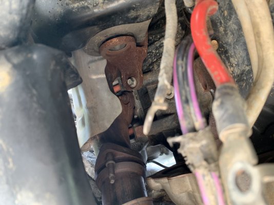
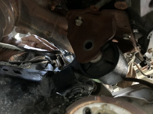
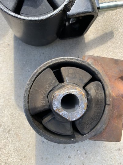
Gen 1 6.2 engine mount / motor mount replacement

Disclaimer: Links on this page pointing to Amazon, eBay and other sites may include affiliate code. If you click them and make a purchase, we may earn a small commission.

PD1744

Full Access Member
Joined
Jan 21, 2020
Posts
290
Reaction score
591
Location
SC
Finally took this on over the weekend and it was quite the job. If you think it's something that you could knock out in like 4 hours (like I did), you'd likely be incorrect. I've done quite a few jobs, some decently big, and I'd probably still put this one at like a 8 or 9/10 for my mechanical ability. This is my attempt at actually providing a contribution to the forum and hopefully giving useful insight. It took me with some help from an equally mechanically apt friend the majority of this weekend to knock this out. You've been warned.

Disclaimer: This is a 'how I did it' not so much a 'how to'. I take no responsibility for anybody messing anything up. Could there be a better way get to the job done? Certainly.

That's out of the way, so let's go.

PULL THE INTAKE

- Depressurize the fuel system. You're supposed to do that by disconnecting the fuel control module located on the crossmember above your spare tire, cranking the truck until it dies, and try to re-crank it a few times. However my connector wouldn't budge from years of mud and just age, so I tried to do the same by just pulling the fuel pump relay (#70 for those that have done the fuse 27 thing). That may or may not have worked... But I'll say that there wasn't enough pressure for me to lose an eye when I carefully opened the fuel line.

- You could drain the cooling system. I did not. I managed the get the thing out without pulling the t-stat housing, but it was tight.

- I unhooked the intake tube from the plenum box and uncliped the filter box cap and swung it out of the way. Then plucked the plenum box out (2 vacuum lines). I think it's just held in from by two small screws (8mm maybe)
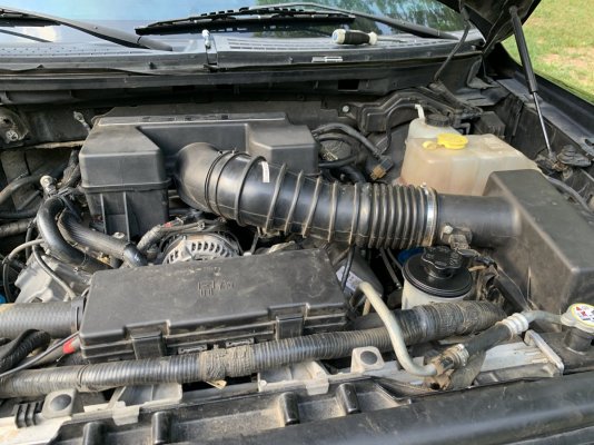
IMG_9113.JPG

- Remove the alternator. 4 bolts (13mm I think. If not then 15 lol. Can't remember). You might think that you can wiggle it out without removing this. You can not.
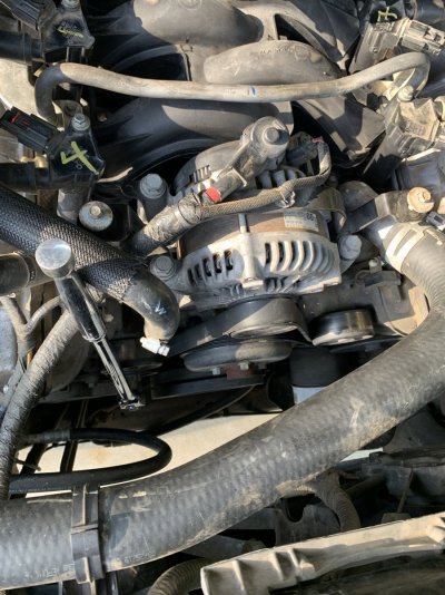
IMG_9164.JPG

- Remove the alternantor cradel. (4x 10mm maybe)
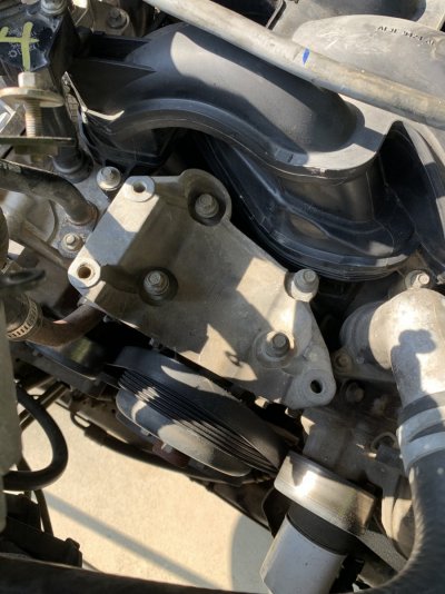
IMG_9163.JPG

- Pull the ignition coils (1x 8mm per coil). I left these attached to the wires and just moved them out of the way. Same with the alternator.
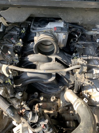
IMG_9162.JPG

- Disconnect the fuel supply line (the one with the blue locking tab on the driver side rail, and the 4x 8mm bolts that hold the fuel rails down, the injector connectors, and yank it or wait and pull it with the manifold.
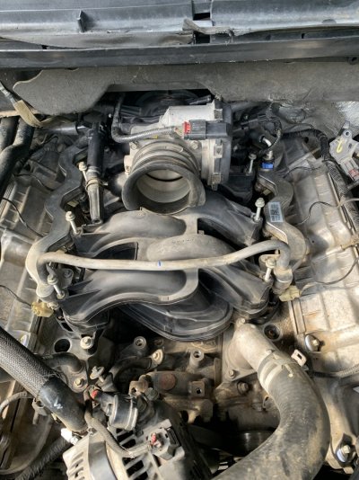
IMG_9161.JPG

Cont...
 
Last edited:
OP
OP
PD1744

PD1744

Full Access Member
Joined
Jan 21, 2020
Posts
290
Reaction score
591
Location
SC
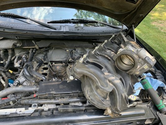
- You could unbolt the throttle body here (4 bolts). I did not. Disconnect the throttle connector. Disconnect the brake booster vacuum line, disconnect the purge valve hose, connector, and PCV tube. There are 4 wiring harness connectors coming through the rear of the intake manifold. I think I managed to dislodge 1 without breaking it. Loosen the 12 manifold bolts (8mm) and remove. All that to get to here:

IMG_9115.JPG

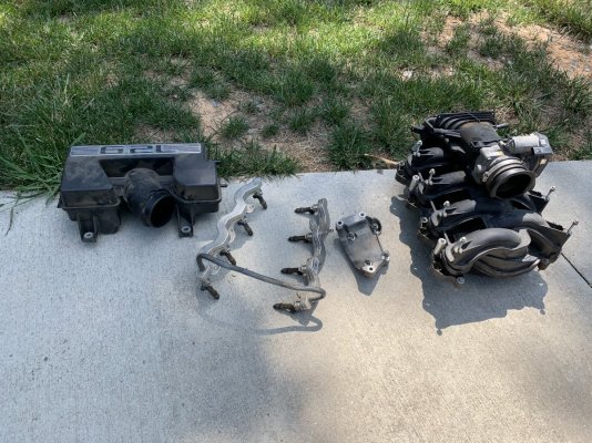
What had to come out to get to this point:

IMG_9116.JPG

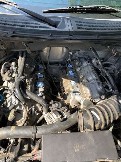
Not a bad idea to plug these up:

IMG_9158.JPG


REMOVE THE STARTER

- My favorite thing to do on these trucks. **If you've not done so yet, I'd highly recommend disconnecting the battery at this point**

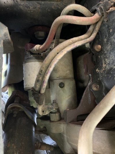
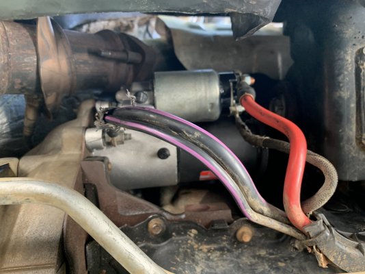
- Maybe take a pic to see how it was wired (or just use mine).

IMG_9117.JPG

- Disconnect the wiring. 2x 13mm And I think a 10mm. Again, make sure you've disconnected the battery.

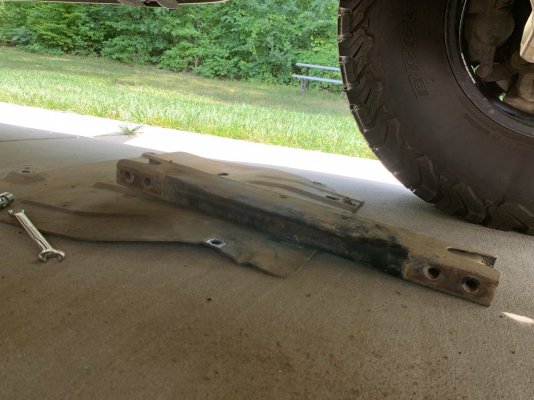
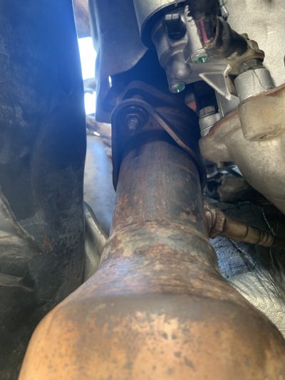
* Tip, unbolt the exhaust flange (manifold to cat 15mm), drop both skids, and unbolt the engine cross member to give yourself as much room to work as possible.

IMG_9119.JPG

Cont...
 
Last edited:
bubbarob

Full Access Member
Joined
Apr 15, 2022
Posts
92
Reaction score
108
Location
DFW
Geez, you weren't kidding with the 8-9/10. Just kept getting more involved the more I scrolled down.
Luckily I think I'm still good with my mounts, but not looking forward to the day when they need to be replaced
 
OP
OP
PD1744

PD1744

Full Access Member
Joined
Jan 21, 2020
Posts
290
Reaction score
591
Location
SC
If you made it this far, say a prayer, because this is where the fun starts. This is the second Raptor starter I've done and I honesty wish to never ever do one again. 3x 13mm's. Bottom one (stud) is okay, middle one not too terrible, top one good luck!

* Tip - removing the splash guards and tires on both sides would be helpful. I only removed the driver side front tire.

The first time, I believe we came through the wheel well and put a wrench on it blind getting a tiny turn at a time. This time I came from the bottom (blind again) and use the right combination of socket/extension/ratchet. Broke one 1/4 drive socket because the bolts were so tight. Used a 3/8" drive adapted down to 1/4" with a small extension and my handy 1/4" drive 144 tooth Husky ratchet. Was the right combo. Your tool kit may offer something better. Perhaps a long reach, small headed electric/pneumatic ratchet with the right length extension.

FRONT DRIVE SHAFT

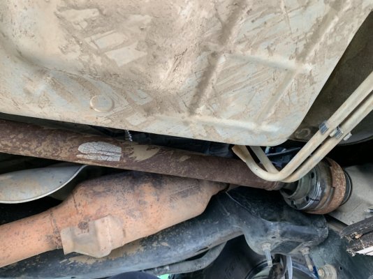
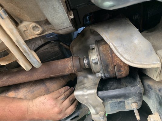
- Just marked and unbolted it from the diff and let it hang. These were small, I think 10mm. Removing the heat shield here is helpful.

IMG_9120.JPG

SUPPORT THE ENGINE

- If you have one of those engine support bars you should use that. While I have access to one, I opted to use a jack with a piece of wood to lift it from the bottom.

- Unbolt the exhaust flange on the driver side.

- Loosen the transmission mounts. I think these were 18mm. Use hand tools instead of impact here.

IMG_9156.JPG

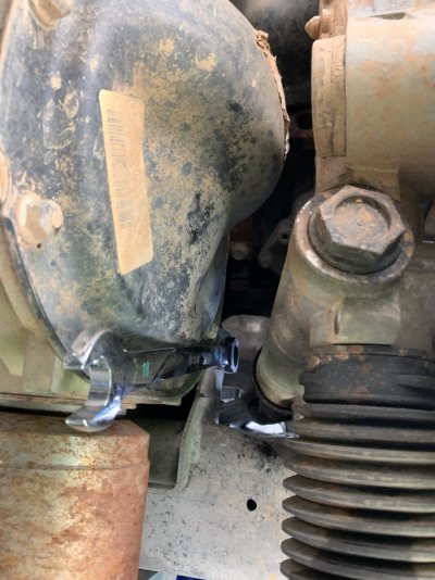
- Break the driver side motor mount through bolt (24mm) loose using hand tools. They say that if you impact them, it can cause damage to the bracket that mounts to the block. You should be able to see it just above the diff.

- Break the passenger side motor mount through bolt with hand tools and remove.

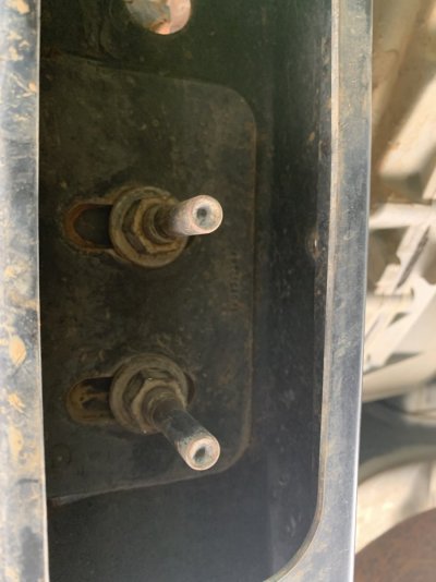
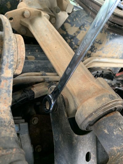
- Remove the two lower nuts (18mm?) on the right hand motor mount. The studs may or may not come out with it. Then remove those studs. They are external torx, which I don't have, but I put a 12pt 10mm ratcheting wrench on it and it worked fine.


LOWER THE DIFF

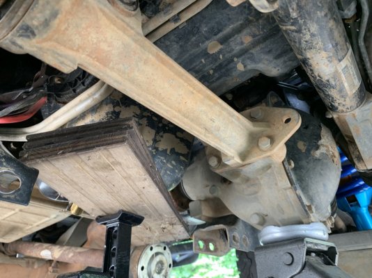
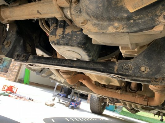
- Place a jack under the front pumpkin to support it (yes, I used two jacks).

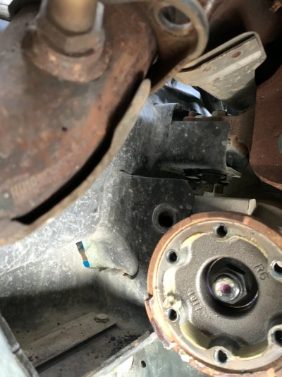
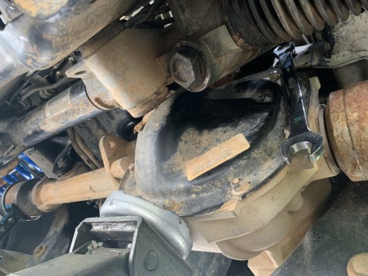
- Next tricky part. Unbolt the upper carrier mount bolt (18mm). You will need to turn the steering column so that the U-joint clears. This part definitely helps to have two people. It's super tight and you will have to wiggle it... just a little bit.

IMG_9122.JPG

- Remove the second diff bolt at the extension tube.

IMG_9123.JPG

-And the last one is on the back side, I believe right here (already removed):

IMG_9125.JPG

NOTE - be careful of any vacuum lines attached to the carrier when lowering the diff. I may or may not have messed up here. We'll see.

Dropping the diff will allow you access to the passenger side lower front bracket mount bolt.
 
Last edited:
OP
OP
PD1744

PD1744

Full Access Member
Joined
Jan 21, 2020
Posts
290
Reaction score
591
Location
SC
AC COMPRESSOR

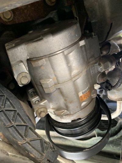
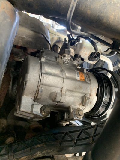
- Unbolt (3x 10mm I think) and unplug the A/C compressor. I just sort of let it hang from the refrigerant lines and shove it forward to access the front bracket bolts on the passenger side.

IMG_9127.JPG


PASSENGER SIDE MOUNT

This was my rig. One jack to lower the diff and the other to raise the engine. Pull all motor mount through bolts at this point if you haven't yet. Raise the engine as much as you can.

IMG_9126.JPG

- unbolt the passenger side engine bracket 3x 13mm.

2 up front way up there

IMG_9128.JPG

and one in the back

IMG_9129.JPG

Then remove the right side motor mount. We pulled the bracket and mount together out toward the rear of the vehicle ^this side^. You better hope you played a lot of Tetris back in the day. Shit toit.


DRIVER SIDE MOTOR MOUNT

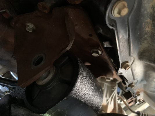
- Next hard part. Remove the 3x 18mm motor mount to frame bolts. They say not to re-use these, however when I looked up the P/N W712805-S439 , they say they had been discontinued without any reference of a replacement. So that's cool. However I do believe I found the part that superseded these. After the fact of course. This one. You can see the bolts in the above pic where I showed the rear diff mount bolt. The mount is tear drop shaped and the skinny end mounts to the frame. This is the set-up that worked for us:

IMG_9142.JPG

This one is pretty blind as well. Going through the wheel well. Removing the tire was helpful. Removing the splash shield would be helpful (we did not). Removing the exhaust manifold heat shield was pretty necessary in order to extract the bolts all the way, however you can pretty much count on those little screws (2x 10 or 8mm) snapping.
 
Last edited:
OP
OP
PD1744

PD1744

Full Access Member
Joined
Jan 21, 2020
Posts
290
Reaction score
591
Location
SC
- Unbolt the bracket on the block. You can see 3 in this pic 13mm, I believe there is one more above the forward most one. The one in the center is pretty fun.

IMG_9149.JPG


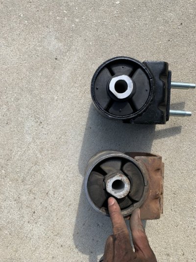
Here's what we discovered:

IMG_9130.JPG

IMG_9134.JPG


Both sides completely wrecked. I did not use OEM parts and I can't remember why. I've had these parts on hand for a very long time, probably since the beginning of my engine build. I think parts weren't available at the time. Very happy to see this as it makes the work worth it and I'm 95% certain is the cause the the vibration issue I've been chasing since I bought this thing.

PASSENGER SIDE INSTALLATION

- Clean all the mating surfaces.

- Install the mount bracket to the block. 46 lb-ft.

- Install the motor mount to the frame with 2 studs (133 lb-in) and two nuts (129 lb-ft)

- I sort of held off installing the studs and lower nuts.


DRIVER SIDE INSTALLATION

- Clean mating surfaces

- Install the mount bracket to the block. 46 lb-ft.

- Install the motor mount to the frame. 129 lb-ft TIP - Pay attention as there is a little bar on the bottom side of the mount that will index with a slot on the frame side. You'll feel it drop and tab in.

At this point we lowered the engine to get the through bolts in (blue thread locker). Tighten both through bolts to 258 lb-ft with hand tools.


DIFF

-Raise and reinstall the diff. 3x 18mm to 85 lb-ft

IMG_9150.JPG


COMPRESSOR

-Reinstall (18 lb-ft) and reconnect compressor.

IMG_9151.JPG

And look, I'm providing torque specs for reference, but in all honesty due to the access to these fasteners, many of them received guten tight torque.
 
Last edited:
OP
OP
PD1744

PD1744

Full Access Member
Joined
Jan 21, 2020
Posts
290
Reaction score
591
Location
SC
-Reinstall drive shaft, heat shields, tires, etc. whatever you needed to remove to gain better access

IMG_9152.JPG

- Tighten transmission mount nuts 76 lb-ft with hand tools.

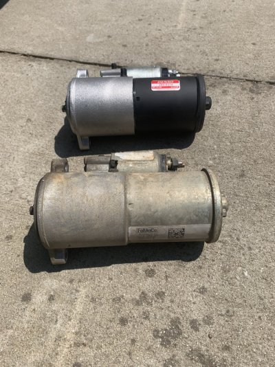
- Install starter. I put in a new one in hopes to not have to do this again.

IMG_9153.JPG

IMG_9154.JPG

- Reinstall Y-pipe flange nuts 4x 15mm 30 lb-ft

IMG_9155.JPG

- Re-install engine cross member

IMG_9157.JPG

I opted to withhold reinstalling the skids for now until I know everything is okay.
 
Top