
I recently installed new Steering Knuckles with gussets from SDHQ and SDHQ tie rods. For a full write up on why gusseted steering knuckles are a viable and important upgrade visit this thread:
http://www.fordraptorforum.com/f9/bending-breaking-steering-knuckle-28639/


Tools needed:
Knuckle only:
8mm socket (brake rotor dust shield, wheel hub speed sensor bracket, IWE actuator)
10mm socket (brake line + vac line bracket)
21mm wrench or 21mm deep well (upper ball joint, brake caliper, tie rod)
24mm wrench or 24mm deep well (lower ball joint)
18mm socket (wheel hub)
13mm socket (axle retainer nut)
5mm Allen Wrench (wheel hub speed sensor)
BFH (Big Friendly Hammer)
Razor blade
Bungee Cord
Red Loctite
Tie Rod:
Factory Removal:
21mm wrench or 21mm deep well
Hook tool
Cutters/Razor Blade
Large Channel Lock pliers or Plumber's Wrench
Adjustable wrench
SDHQ Tie Rod Installation:
19mm Wrench
19mm Socket
21mm Socket
Adjustable wrenches
15mm wrench (double shear connection only)
15mm socket (double shear connection only)
Red Loctite
1 3/4 hose clamps (x2)
3" hose clamps (x2)
Anti-Sieze
Red Loctite
Difficulty: 1 2 3 4 5 6 7 8 9 10
Time: 3-8 hours
- Experienced tech with a lift and air tools, 3-4 hours for both sides
- Leave the beer in the fridge for this one
I will begin with just the knuckle replacement. If you plan on upgrading your tie rods, now would be the time to think about doing it. If you replace your knuckles with the gusseted setup from SDHQ, you will have the option of doing a double shear connection for the outer tie rod heim. You can do it later, but doing it later will require disassembly of your brakes and possibly some drilling if you don't order the correct gusset kit.
The day before my install, I decided to give the new knuckles and fresh coat of paint and MPHD. I primed and painted with Rust-o-Leum industrial enamel and applied a coat of AmsOil MPHD after 24 hours.


1. Securely lift your Raptor and remove the wheel(s). Apply the e-brake and use wheel chocks if you're using jack stands.

2. Remove the brackets from the knuckle which hold the brake lines, IWE vacuum lines and wheel hub speed sensor lines using a 10mm and 8mm socket. Separate the hub speed sensor line from the bracket by releasing the black plastic clip. Release the vacuum line clip from the top of the knuckle.

3. Remove your brake caliper by removing the 2 bolts on the back side of the caliper. 21mm socket. Use a bungee cord to hang your brake caliper out of the way. Make sure not to stretch or strain the brake line.

4. Remove the brake rotor. Use a BFH to gently tap the brake rotor from behind to loosen it from the hub. Rotate if necessary.

5. Remove the brake dust shield. 3 small bolts - 8mm socket.

6. Clean the area around the wheel hub. Use a long bristled scrub brush or a rag to clean any excess dirt/mud.
7. Remove the hub wheel speed sensor from the hub using a 5mm Allen Wrench. Also, remove the IWE vacuum line. Secure out of the way.


8. Remove the wheel hub grease cap. With a pair of pliers or channel locks, gently grasp the cap, pull and wiggle.

9. Loosen the UCA upper ball joint nut with a 21mm wrench or deep well socket and release the taper. Loosen the nut but leave a few threads engaged. Firmly smack the side of the knuckle near the UCA stud with your BFH. After a few hits the pin should release from the knuckle.

10. Loosen the outer tie rod end. Same process as the UCA, 21mm wrench or deep well socket and smack the knuckle near the tie rod with your BFH.

11. Loosen the lower ball joint nut with a 24mm wrench or deep well socket (15/16 works too). Once again, same process. Leave a few threads engaged and smack the lower control arm and knuckle around the lower ball joint.

*Tip. If a few firm hits doesn't release the lower ball joint, don't start smashing up the lower control arm. Use a floor jack or a bottle jack and place it under the lower ball joint stud. Apply moderate pressure to press the stud up and start smacking the area with your BFH again.
12. Using a 13mm socket, remove the axle half shaft nut.

13. Remove the wheel hub by removing the 4 bolts on the back side of the knuckle. 18mm socket. Lightly tap the back of the wheel hub to slide it out of the assembly. Be cautious not to damage the o-ring.


14. Remove the nuts from the upper ball joint, tie rod and lower ball joint. You will now be able to remove the steering knuckle from the truck.

15. Transfer the IWE actuator from your old knuckle to your new knuckle. 3 bolts - 8mm.


---------------------------------------------------------
To reinstall the knuckle:
16. Pass the lower ball joint stud through the knuckle and loosely install the nut to support the knuckle. You can use a floor jack to push against the knuckle to help seat the lower ball joint.
17. Pass the axle shaft through the knuckle and IWE actuator. Be sure to line up the splines.
18. Once the splines are lined up, push the top of the knuckle up and seat the upper ball joint pin. Loosely secure the nut.

19. Reinstall the wheel hub. *Carefully* align the axle shaft through the center of the hub and slide the hub into the knuckle. Gently wiggle or rotate the hub to ensure the o-ring doesn't get hung up and the splines will line up.
20. Loosely secure the axle retainer nut and 4 main hub bolts. Double check again that all of the splines line up and turn the hub to ensure the axle is spinning. Tighten down the 4 hub bolts (18mm socket) a little each at a time and torque to 129 lb/-ft. Retainer nut to 20 lb-ft (13mm socket). Reinstall wheel hub grease cap, align and tap with a hammer.


21. Secure the upper ball joint nut - 21mm. This is a Nylock nut, if you are reusing the nut and the nylon insert appears to be chewed up it's recommended you use Blue Loctite. Torque to 85 lb-ft.
22. Secure the lower ball joint nut - 24mm. Inspect nylon insert. Blue Loctite if necessary. Torque to 111 lb-ft.
************************************
If you are installing SDHQ tie rods with double shear connection, complete the installation of the tie rods before proceeding to steps 23-29
************************************
23. Secure outer tie rod end to knuckle - 21mm. Inspect nylon insert. Blue Loctite if necessary. Torque to 85 lb-ft.
24. Reinstall hum wheel speed sensor and brake dust shield. 5mm Allen wrench and 3 bolts - 8mm socket.
25. Reinstall brake rotor. Place over wheel studs and press against the hub.
26. Reinstall brake caliper. Slide brake caliper over the rotor and align with the caliper anchor plate. Apply Red Loctite to the 2 brake caliper bolts. Secure to 184 lb-ft - 21mm socket.
27. Reinstall wheel speed sensor + vacuum/brake line brackets to the knuckle using a 10mm and 8mm socket. Reinstall the vacuum line to the IWE.
28. Double and triple check all bolts. You DO NOT want any of this stuff coming loose.

29. Reinstall wheel/tire.
SDHQ TIE ROD WITH DOUBLE SHEAR CONNECTION
If you are simply replacing your tie rod and you're not utilizing the write up above for replacing your knuckles see step 1a otherwise proceed to 2a:
1a. If you haven't done so already, remove the outer tie rod connection (see #10 above).
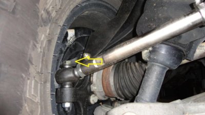
2a. Remove the tie rod boot from the steering rack. The inner end of the boot is secured with a non-reusable crimp clamp. Either cut the crimp or use a hook tool to grab the crimp and pull toward you.

3a. Compress the tie rod boot to expose the inner tie rod end. Use a pair of large Channel Locks or a Plumber's wrench to loosen the inner tie rod nut. You should be able to remove the tie rod by hand after loosening the tie rod from the steering rack. Remove the factory tie rod and disassemble it.

4a. You will need to cut the the tie rod boot off the factory tie rod to reuse on your new tie rods. Release spring clamp from the outside of the boot and trim around the indent. Loosen the tie rod jam nut and separate the inner and outer tie rods. Remove the jam nut from the outer tie rod and slide the boot off.

5a. Prepare your tie rod boot for installation on the SDHQ tie rods. Using a razor blade, carefully trim the tapered end of the boot approximately 1/8" from the end. Set aside for now.

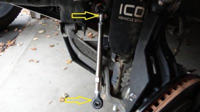
6a. Install the tie rod clevis to the steering rack as shown. Use Red Loctite on this bolt and secure with a 21mm socket. Tighten until the bolt head sits tightly against the clevis. Make sure the clevis is as straight as possible.

7a. Slide the modified tie rod boot over the SDHQ tie rod and assemble the heim ends. Start by threading both heim shanks into the tie rod half way and adjust equally from there. Use anti-seize on the threads!
*Note: The SDHQ tie rod comes with a black rubber dust boot for the outer heim joints. It will be easiest to install the dust boot on the heim prior to threading it in to the tie rod. The easiest method for installing the dust boot is to pass the shank of the heim joint through one side of the boot and out the bottom. You can then stretch and maneuver the dust boot over the heim joint.
Assembled only for illustration purposes - DON'T FORGET THE BOOT!

8a. With the jam nuts loose, first connect the inner heim joint to the clevis using the supplied spacers and hardware. The nuts supplied are Stover nuts (steel lock nuts) which essentially deform the bolt threads as you tighten them down. Red Loctitie is still recommended. 19mm wrench and socket. Torque to 106 lb-ft.

9a. Install the outer tie rod heim joint to the knuckle with the supplied spacers. If you are using the double shear connection plate, do not install the bolt yet.
10a. Install the double shear connection plate to the knuckle gusset using a 15mm socket and 15mm wrench. This is why we left the brakes off, as accessing these bolts is nearly impossible with the brake dust shield installed.
-Install and secure the 2 bolts on the side of the plate first, facing outward.
-Install the bolt on the top side of the plate last.

11a. Pass the outer heim joint bolt through and secure to the knuckle using a 19mm wrench and 19mm socket. Torque to 106 lb-ft. Red Loctitie.

12a. Visually align your toe by turning the tie rod. Before securing the jam nuts, make sure the heim joints are as straight as possible. Secure the jam nuts.

13a. Install tie rod boot hose clamps. It may be beneficial to slightly heat the outer end of the boot before and during installation of the new hose clamp to help re-form the tapered end.

*******PROCEED TO Steps 23-29 above************
14a. You will likely need an alignment. Take to a trusted alignment shop and again mention to the tech that the heim joints should be straight once the toe is aligned.


http://www.fordraptorforum.com/f9/bending-breaking-steering-knuckle-28639/
Tools needed:
Knuckle only:
8mm socket (brake rotor dust shield, wheel hub speed sensor bracket, IWE actuator)
10mm socket (brake line + vac line bracket)
21mm wrench or 21mm deep well (upper ball joint, brake caliper, tie rod)
24mm wrench or 24mm deep well (lower ball joint)
18mm socket (wheel hub)
13mm socket (axle retainer nut)
5mm Allen Wrench (wheel hub speed sensor)
BFH (Big Friendly Hammer)
Razor blade
Bungee Cord
Red Loctite
Tie Rod:
Factory Removal:
21mm wrench or 21mm deep well
Hook tool
Cutters/Razor Blade
Large Channel Lock pliers or Plumber's Wrench
Adjustable wrench
SDHQ Tie Rod Installation:
19mm Wrench
19mm Socket
21mm Socket
Adjustable wrenches
15mm wrench (double shear connection only)
15mm socket (double shear connection only)
Red Loctite
1 3/4 hose clamps (x2)
3" hose clamps (x2)
Anti-Sieze
Red Loctite
Difficulty: 1 2 3 4 5 6 7 8 9 10
Time: 3-8 hours
- Experienced tech with a lift and air tools, 3-4 hours for both sides
- Leave the beer in the fridge for this one
I will begin with just the knuckle replacement. If you plan on upgrading your tie rods, now would be the time to think about doing it. If you replace your knuckles with the gusseted setup from SDHQ, you will have the option of doing a double shear connection for the outer tie rod heim. You can do it later, but doing it later will require disassembly of your brakes and possibly some drilling if you don't order the correct gusset kit.
The day before my install, I decided to give the new knuckles and fresh coat of paint and MPHD. I primed and painted with Rust-o-Leum industrial enamel and applied a coat of AmsOil MPHD after 24 hours.
1. Securely lift your Raptor and remove the wheel(s). Apply the e-brake and use wheel chocks if you're using jack stands.
2. Remove the brackets from the knuckle which hold the brake lines, IWE vacuum lines and wheel hub speed sensor lines using a 10mm and 8mm socket. Separate the hub speed sensor line from the bracket by releasing the black plastic clip. Release the vacuum line clip from the top of the knuckle.
3. Remove your brake caliper by removing the 2 bolts on the back side of the caliper. 21mm socket. Use a bungee cord to hang your brake caliper out of the way. Make sure not to stretch or strain the brake line.
4. Remove the brake rotor. Use a BFH to gently tap the brake rotor from behind to loosen it from the hub. Rotate if necessary.
5. Remove the brake dust shield. 3 small bolts - 8mm socket.
6. Clean the area around the wheel hub. Use a long bristled scrub brush or a rag to clean any excess dirt/mud.
7. Remove the hub wheel speed sensor from the hub using a 5mm Allen Wrench. Also, remove the IWE vacuum line. Secure out of the way.
8. Remove the wheel hub grease cap. With a pair of pliers or channel locks, gently grasp the cap, pull and wiggle.
9. Loosen the UCA upper ball joint nut with a 21mm wrench or deep well socket and release the taper. Loosen the nut but leave a few threads engaged. Firmly smack the side of the knuckle near the UCA stud with your BFH. After a few hits the pin should release from the knuckle.
10. Loosen the outer tie rod end. Same process as the UCA, 21mm wrench or deep well socket and smack the knuckle near the tie rod with your BFH.
11. Loosen the lower ball joint nut with a 24mm wrench or deep well socket (15/16 works too). Once again, same process. Leave a few threads engaged and smack the lower control arm and knuckle around the lower ball joint.
*Tip. If a few firm hits doesn't release the lower ball joint, don't start smashing up the lower control arm. Use a floor jack or a bottle jack and place it under the lower ball joint stud. Apply moderate pressure to press the stud up and start smacking the area with your BFH again.
12. Using a 13mm socket, remove the axle half shaft nut.
13. Remove the wheel hub by removing the 4 bolts on the back side of the knuckle. 18mm socket. Lightly tap the back of the wheel hub to slide it out of the assembly. Be cautious not to damage the o-ring.
14. Remove the nuts from the upper ball joint, tie rod and lower ball joint. You will now be able to remove the steering knuckle from the truck.
15. Transfer the IWE actuator from your old knuckle to your new knuckle. 3 bolts - 8mm.
---------------------------------------------------------
To reinstall the knuckle:
16. Pass the lower ball joint stud through the knuckle and loosely install the nut to support the knuckle. You can use a floor jack to push against the knuckle to help seat the lower ball joint.
17. Pass the axle shaft through the knuckle and IWE actuator. Be sure to line up the splines.
18. Once the splines are lined up, push the top of the knuckle up and seat the upper ball joint pin. Loosely secure the nut.
19. Reinstall the wheel hub. *Carefully* align the axle shaft through the center of the hub and slide the hub into the knuckle. Gently wiggle or rotate the hub to ensure the o-ring doesn't get hung up and the splines will line up.
20. Loosely secure the axle retainer nut and 4 main hub bolts. Double check again that all of the splines line up and turn the hub to ensure the axle is spinning. Tighten down the 4 hub bolts (18mm socket) a little each at a time and torque to 129 lb/-ft. Retainer nut to 20 lb-ft (13mm socket). Reinstall wheel hub grease cap, align and tap with a hammer.
21. Secure the upper ball joint nut - 21mm. This is a Nylock nut, if you are reusing the nut and the nylon insert appears to be chewed up it's recommended you use Blue Loctite. Torque to 85 lb-ft.
22. Secure the lower ball joint nut - 24mm. Inspect nylon insert. Blue Loctite if necessary. Torque to 111 lb-ft.
************************************
If you are installing SDHQ tie rods with double shear connection, complete the installation of the tie rods before proceeding to steps 23-29
************************************
23. Secure outer tie rod end to knuckle - 21mm. Inspect nylon insert. Blue Loctite if necessary. Torque to 85 lb-ft.
24. Reinstall hum wheel speed sensor and brake dust shield. 5mm Allen wrench and 3 bolts - 8mm socket.
25. Reinstall brake rotor. Place over wheel studs and press against the hub.
26. Reinstall brake caliper. Slide brake caliper over the rotor and align with the caliper anchor plate. Apply Red Loctite to the 2 brake caliper bolts. Secure to 184 lb-ft - 21mm socket.
27. Reinstall wheel speed sensor + vacuum/brake line brackets to the knuckle using a 10mm and 8mm socket. Reinstall the vacuum line to the IWE.
28. Double and triple check all bolts. You DO NOT want any of this stuff coming loose.
29. Reinstall wheel/tire.
SDHQ TIE ROD WITH DOUBLE SHEAR CONNECTION
If you are simply replacing your tie rod and you're not utilizing the write up above for replacing your knuckles see step 1a otherwise proceed to 2a:
1a. If you haven't done so already, remove the outer tie rod connection (see #10 above).
2a. Remove the tie rod boot from the steering rack. The inner end of the boot is secured with a non-reusable crimp clamp. Either cut the crimp or use a hook tool to grab the crimp and pull toward you.
3a. Compress the tie rod boot to expose the inner tie rod end. Use a pair of large Channel Locks or a Plumber's wrench to loosen the inner tie rod nut. You should be able to remove the tie rod by hand after loosening the tie rod from the steering rack. Remove the factory tie rod and disassemble it.
4a. You will need to cut the the tie rod boot off the factory tie rod to reuse on your new tie rods. Release spring clamp from the outside of the boot and trim around the indent. Loosen the tie rod jam nut and separate the inner and outer tie rods. Remove the jam nut from the outer tie rod and slide the boot off.
5a. Prepare your tie rod boot for installation on the SDHQ tie rods. Using a razor blade, carefully trim the tapered end of the boot approximately 1/8" from the end. Set aside for now.
6a. Install the tie rod clevis to the steering rack as shown. Use Red Loctite on this bolt and secure with a 21mm socket. Tighten until the bolt head sits tightly against the clevis. Make sure the clevis is as straight as possible.
7a. Slide the modified tie rod boot over the SDHQ tie rod and assemble the heim ends. Start by threading both heim shanks into the tie rod half way and adjust equally from there. Use anti-seize on the threads!
*Note: The SDHQ tie rod comes with a black rubber dust boot for the outer heim joints. It will be easiest to install the dust boot on the heim prior to threading it in to the tie rod. The easiest method for installing the dust boot is to pass the shank of the heim joint through one side of the boot and out the bottom. You can then stretch and maneuver the dust boot over the heim joint.
Assembled only for illustration purposes - DON'T FORGET THE BOOT!
8a. With the jam nuts loose, first connect the inner heim joint to the clevis using the supplied spacers and hardware. The nuts supplied are Stover nuts (steel lock nuts) which essentially deform the bolt threads as you tighten them down. Red Loctitie is still recommended. 19mm wrench and socket. Torque to 106 lb-ft.
9a. Install the outer tie rod heim joint to the knuckle with the supplied spacers. If you are using the double shear connection plate, do not install the bolt yet.
10a. Install the double shear connection plate to the knuckle gusset using a 15mm socket and 15mm wrench. This is why we left the brakes off, as accessing these bolts is nearly impossible with the brake dust shield installed.
-Install and secure the 2 bolts on the side of the plate first, facing outward.
-Install the bolt on the top side of the plate last.
11a. Pass the outer heim joint bolt through and secure to the knuckle using a 19mm wrench and 19mm socket. Torque to 106 lb-ft. Red Loctitie.
12a. Visually align your toe by turning the tie rod. Before securing the jam nuts, make sure the heim joints are as straight as possible. Secure the jam nuts.
13a. Install tie rod boot hose clamps. It may be beneficial to slightly heat the outer end of the boot before and during installation of the new hose clamp to help re-form the tapered end.
*******PROCEED TO Steps 23-29 above************
14a. You will likely need an alignment. Take to a trusted alignment shop and again mention to the tech that the heim joints should be straight once the toe is aligned.