
ZBoater
FRF Addict
- Joined
- Mar 9, 2014
- Posts
- 1,980
- Reaction score
- 865
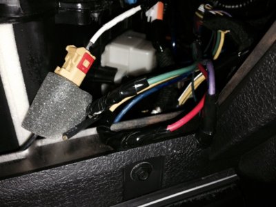
I'm about to embark on what it seems like a daily modding adventure. Today's episode is wiring the newly mounted KC Slimlites mounted on Alternative Offroad hood mounts.
These lights are the 130W version. According to the KC website, they draw 10.8 amps.
What is the AMP Draw of my KC lights?
According to the excellent how to thread on wiring the upfitter switches
http://www.fordraptorforum.com/f170/wire-raptor-aux-upfitter-switches-20335/
Switch #3 is 15A. So I'm picking that one.
Seems too easy. Am I missing something?
---------- Post added at 04:50 PM ---------- Previous post was at 04:39 PM ----------
I'm assuming there's no fuses, no relays, nothing special I need to do. Just connect the hot wire and the ground wire and... Let there be light!
I hope.
Last edited:


")