
KryptosXLayer2
Full Access Member
So you will probably want to install a diode....
I'd highly recommend using the diode.
I used three diodes....
You also need two diodes to prevent backfeed to the combined circuit when using individual switches 1 or 2.
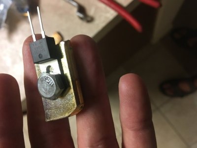
Since everyone here is apparently an electrical engineer and says "use diodes," can we get an idea as to WHAT diodes were used, please? I had to do a calculation the last time I used diodes to make my rear fog light switch work independent of a wired in second set of brake lights on a previous car, so when you all say "use diodes," can we get an idea as to what diodes were used?
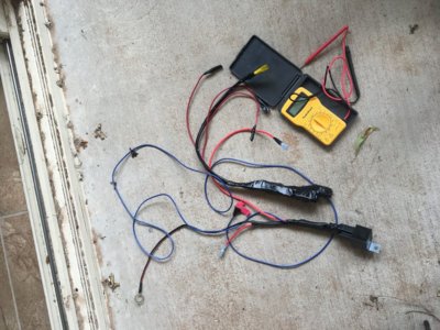
I'm wiring up my OnX6 lights from @4x4TruckLEDs.com soon and would like some additional information. If relays are the way to go, please post a wiring diagram you used to prevent backfeed (I've seen one on another thread I believe). If you used diodes, please identify which one you used and where it was installed in the wiring.
This thread is USELESS with the posts saying to use this or that without saying HOW to use this or WHAT you actually used!