TSB 11-8-4
08/11/11
6R80 TRANSMISSIONS - FLUID LEAK FROM BELL
HOUSING - BUILT ON OR AFTER 4/15/2011
THROUGH 6/8/2011
FORD:
2012 Mustang
2011 Expedition, F-150
LINCOLN:
2011 Navigator
The article supersedes TSB 11-7-18 to update the Part List.
ISSUE
Some 2011 F-150, Expedition, Navigator and 2012 Mustang vehicles equipped with the 6R80 automatic transmission and built on or after 4/15/2011 through 6/8/2011 may exhibit a transmission fluid leak from the bell housing area.
ACTION
Follow the Service Procedure steps to correct the condition.
SERVICE PROCEDURE
1. With the vehicle in neutral, position it on a hoist and raise vehicle. For additional information, refer to Workshop Manual (WSM), Section 100-02.
2. Remove the transmission fluid pan to check the condition of the fluid.
a. If the fluid smells burnt or very dark in color discontinue with this article, Refer to WSM, Section 307-01 diagnosis by symptoms for normal diagnostics.
b. If transmission fluid is red and does not smell burnt proceed to Step 3.
3. Remove the transmission, Refer to WSM, Section 307-01.
4. Mount the transmission to holding fixture essential special service tool (ESSI) 307-003.
5. Using ESSI 307-091 remove the torque converter.
6. Remove transmission fluid pan.
7. Remove transmission fluid filter.
View attachment 8497
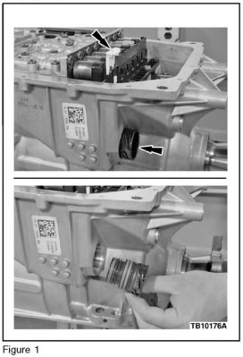
8. Press the release tab and lift up on the main control bulkhead electrical connector retainer to release the bulkhead electrical connector shell. (Figure 1)
9. With the transmission bulkhead electrical connector retainer released, pull the outer shell of the bulkhead electrical connector out of the transmission.
10. Remove the 11 main control fasteners.
11. Remove the main control assembly.
a. Thermal valve assembly may fall out.
View attachment 8498
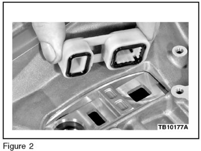
12. Remove the front pump adapter seal. (Figure 2)
13. Remove and discard the 13 front pump-to-case bolts and washers.
14. Using ESSI 307-553 and 100-001 remove pump from case.
a. The selective shim may come out while removing the front pump.
15. Place pump assembly on bench and note orientation of pump body to pump assembly to aid in reassembly.
16. Remove and discard the outer pump assembly 0-ring seal.
View attachment 8499
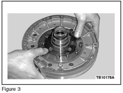
17. Loosen all 11 pump body to pump assembly fasteners and carefully push down on the loosened fasteners to remove pump and gear assembly and discard. (Figure 3)
View attachment 8500
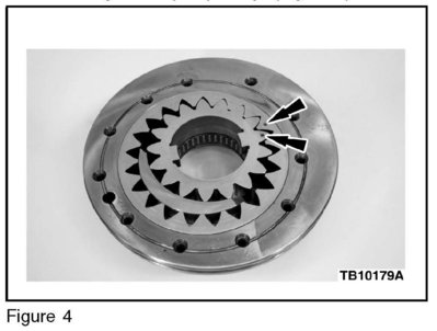
a. Verify both inner and outer gears have the Dot facing up on the new pump body and gears. Use care to keep pump gears from falling out of pump body. (Figure 4)
View attachment 8501
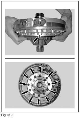
18. Lube new pump body and gear assembly outer pump body 0-ring with clean transmission fluid and align new pump body and gear assembly to pump plate and stator and carefully install into the pump plate and stator. (Figure 5)
19. Install the pump plate assembly-to-front pump body bolts. Tighten to 15 N.m (133 lb-in).
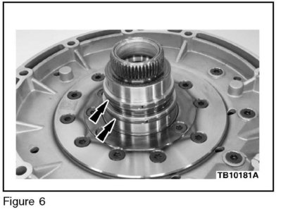
20. Inspect pump stator seals replace if damaged. (Figure 6)
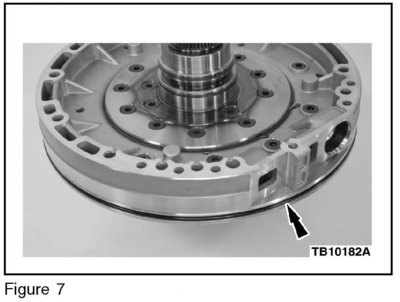
21. Install a new pump body outer 0-ring seal. (Figure 7)
22. Reinstall the selective shim
23. Lubricate the transmission case pump bore with petroleum jelly.
24. Using ESSI 307-533, position the pump assembly in the case and rotate the pump to insert the pump splines into the front planetary sun gear. Rotate the pump to align the pump-to-case bolts and push the pump into the case.
25. Install 13 new front pump-to-case bolts and washers. Tighten in a crisscross pattern. Tighten to 10 N.m (89 lb-in).
26. Install the front pump adapter seal.
27. Add 11.8 cl (4 oz.) of clean transmission fluid through filter inlet to prime the pump.
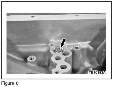
28. Install the thermal bypass valve into the case. (Figure 8)
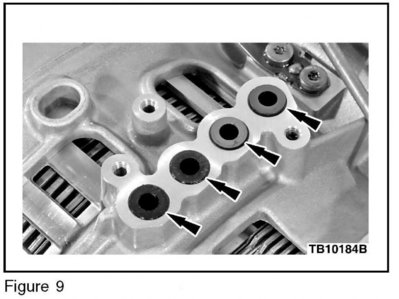
a. Verify clutch feed tubes are position correctly. (Figure 9)
29. Align the manual valve with manual valve linkage and install the main control.
30. Install the 11 main control assembly bolts and tighten to 8 N~m (71 lb-in).
31. With the release tab up and unlocked, push the outer shell of the bulkhead electrical connector into the transmission. Make sure the bulkhead connector is fully seated into the molded lead frame.
32. Press down on the tab and lock the outer shell of the bulkhead electrical connector in place. Make sure the locking tab is securely locked.
33. Install transmission fluid filter.
a. The fluid pan gasket can be reused if not damaged.
34. Install the transmission fluid pan. Tighten in a crisscross pattern. Tighten to 12 N.m (106 lb-in).
35. Install the torque converter.
36. Install the transmission, Refer to WSM, Section 307-01.
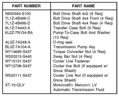
Parts Block
WARRANTY STATUS: Eligible Under Provisions Of New Vehicle Limited Warranty Coverage
IMPORTANT : Warranty coverage limits/policies are not altered by a TSB. Warranty coverage limits are determined by the identified causal part.
OPERATION DESCRIPTION TIME
110804A 2012 Mustang: Inspect, 5.6 Hrs.
Replace The Transmission
Pump Gear Assembly
Following The Service
Procedure (Do Not Use
With Any Other Labor
Operations)
110804A 2011 Expedition And 7.0 Hrs.
Navigator 4X2: Inspect,
Replace The Transmission
Pump Gear Assembly
Following The Service
Procedure (Do Not Use
With Any Other Labor
Operations)
110804A 2011 F-150 4X2 3.5L 6.4 Hrs.
GTDI: Inspect, Replace
The Transmission Pump
Gear Assembly Following
The Service Procedure (Do
Not Use With Any Other
Labor Operations)
110804A 2011 F-150 4X2 3.7L 6.5 Hrs.
DOHC: Inspect, Replace
The Transmission Pump
Gear Assembly Following
The Service Procedure (Do
Not Use With Any Other
Labor Operations)
110804A 2011 F-150 4X2 5.0L 6.8Hrs.
TIVCT: Inspect, Replace
The Transmission Pump
Gear Assembly Following
The Service Procedure (Do
Not Use With Any Other
Labor Operations)
110804A 2011 F-150 4X2 6.2L 6.5 Hrs.
OHC: Inspect, Replace
The Transmission Pump
Gear Assembly Following
The Service Procedure (Do
Not Use With Any Other
Labor Operations)
110804A 2011 Expedition 4X4: 8.3 Hrs.
Inspect, Replace The
Transmission Pump Gear
Assembly Following The
Service Procedure (Do Not
Use With Any Other Labor
Operations)
110804A 2011 Navigator 4X4: 8.2 Hrs.
Inspect, Replace The
Transmission Pump Gear
Assembly Following The
Service Procedure (Do Not
Use With Any Other Labor
Operations)
110804A 2011 F-150 4X4 3.5L 7.7Hrs.
GTDI: Inspect, Replace
The Transmission Pump
Gear Assembly Following
The Service Procedure (Do
Not Use With Any Other
Labor Operations)
110804A 2011 F-150 4X4 3.7L 7.7Hrs.
DOHC: Inspect, Replace
The Transmission Pump
Gear Assembly Following
The Service Procedure (Do
Not Use With Any Other
Labor Operations)
110804A 2011 F-150 4X4 5.0L 8.1 Hrs.
TIVCT: Inspect, Replace
The Transmission Pump
Gear Assembly Following
The Service Procedure (Do
Not Use With Any Other
Labor Operations)
110804A 2011 F-150 4X4 6.2L 7.8 Hrs.
OHC: Inspect, Replace
The Transmission Pump
Gear Assembly Following
The Service Procedure (Do
Not Use With Any Other
Labor Operations)
DEALER CODING
CONDITION
BASIC PART NO. CODE
7A104 D8
08/11/11
6R80 TRANSMISSIONS - FLUID LEAK FROM BELL
HOUSING - BUILT ON OR AFTER 4/15/2011
THROUGH 6/8/2011
FORD:
2012 Mustang
2011 Expedition, F-150
LINCOLN:
2011 Navigator
The article supersedes TSB 11-7-18 to update the Part List.
ISSUE
Some 2011 F-150, Expedition, Navigator and 2012 Mustang vehicles equipped with the 6R80 automatic transmission and built on or after 4/15/2011 through 6/8/2011 may exhibit a transmission fluid leak from the bell housing area.
ACTION
Follow the Service Procedure steps to correct the condition.
SERVICE PROCEDURE
1. With the vehicle in neutral, position it on a hoist and raise vehicle. For additional information, refer to Workshop Manual (WSM), Section 100-02.
2. Remove the transmission fluid pan to check the condition of the fluid.
a. If the fluid smells burnt or very dark in color discontinue with this article, Refer to WSM, Section 307-01 diagnosis by symptoms for normal diagnostics.
b. If transmission fluid is red and does not smell burnt proceed to Step 3.
3. Remove the transmission, Refer to WSM, Section 307-01.
4. Mount the transmission to holding fixture essential special service tool (ESSI) 307-003.
5. Using ESSI 307-091 remove the torque converter.
6. Remove transmission fluid pan.
7. Remove transmission fluid filter.
View attachment 8497
8. Press the release tab and lift up on the main control bulkhead electrical connector retainer to release the bulkhead electrical connector shell. (Figure 1)
9. With the transmission bulkhead electrical connector retainer released, pull the outer shell of the bulkhead electrical connector out of the transmission.
10. Remove the 11 main control fasteners.
11. Remove the main control assembly.
a. Thermal valve assembly may fall out.
View attachment 8498
12. Remove the front pump adapter seal. (Figure 2)
13. Remove and discard the 13 front pump-to-case bolts and washers.
14. Using ESSI 307-553 and 100-001 remove pump from case.
a. The selective shim may come out while removing the front pump.
15. Place pump assembly on bench and note orientation of pump body to pump assembly to aid in reassembly.
16. Remove and discard the outer pump assembly 0-ring seal.
View attachment 8499
17. Loosen all 11 pump body to pump assembly fasteners and carefully push down on the loosened fasteners to remove pump and gear assembly and discard. (Figure 3)
View attachment 8500
a. Verify both inner and outer gears have the Dot facing up on the new pump body and gears. Use care to keep pump gears from falling out of pump body. (Figure 4)
View attachment 8501
18. Lube new pump body and gear assembly outer pump body 0-ring with clean transmission fluid and align new pump body and gear assembly to pump plate and stator and carefully install into the pump plate and stator. (Figure 5)
19. Install the pump plate assembly-to-front pump body bolts. Tighten to 15 N.m (133 lb-in).

20. Inspect pump stator seals replace if damaged. (Figure 6)

21. Install a new pump body outer 0-ring seal. (Figure 7)
22. Reinstall the selective shim
23. Lubricate the transmission case pump bore with petroleum jelly.
24. Using ESSI 307-533, position the pump assembly in the case and rotate the pump to insert the pump splines into the front planetary sun gear. Rotate the pump to align the pump-to-case bolts and push the pump into the case.
25. Install 13 new front pump-to-case bolts and washers. Tighten in a crisscross pattern. Tighten to 10 N.m (89 lb-in).
26. Install the front pump adapter seal.
27. Add 11.8 cl (4 oz.) of clean transmission fluid through filter inlet to prime the pump.

28. Install the thermal bypass valve into the case. (Figure 8)

a. Verify clutch feed tubes are position correctly. (Figure 9)
29. Align the manual valve with manual valve linkage and install the main control.
30. Install the 11 main control assembly bolts and tighten to 8 N~m (71 lb-in).
31. With the release tab up and unlocked, push the outer shell of the bulkhead electrical connector into the transmission. Make sure the bulkhead connector is fully seated into the molded lead frame.
32. Press down on the tab and lock the outer shell of the bulkhead electrical connector in place. Make sure the locking tab is securely locked.
33. Install transmission fluid filter.
a. The fluid pan gasket can be reused if not damaged.
34. Install the transmission fluid pan. Tighten in a crisscross pattern. Tighten to 12 N.m (106 lb-in).
35. Install the torque converter.
36. Install the transmission, Refer to WSM, Section 307-01.

Parts Block
WARRANTY STATUS: Eligible Under Provisions Of New Vehicle Limited Warranty Coverage
IMPORTANT : Warranty coverage limits/policies are not altered by a TSB. Warranty coverage limits are determined by the identified causal part.
OPERATION DESCRIPTION TIME
110804A 2012 Mustang: Inspect, 5.6 Hrs.
Replace The Transmission
Pump Gear Assembly
Following The Service
Procedure (Do Not Use
With Any Other Labor
Operations)
110804A 2011 Expedition And 7.0 Hrs.
Navigator 4X2: Inspect,
Replace The Transmission
Pump Gear Assembly
Following The Service
Procedure (Do Not Use
With Any Other Labor
Operations)
110804A 2011 F-150 4X2 3.5L 6.4 Hrs.
GTDI: Inspect, Replace
The Transmission Pump
Gear Assembly Following
The Service Procedure (Do
Not Use With Any Other
Labor Operations)
110804A 2011 F-150 4X2 3.7L 6.5 Hrs.
DOHC: Inspect, Replace
The Transmission Pump
Gear Assembly Following
The Service Procedure (Do
Not Use With Any Other
Labor Operations)
110804A 2011 F-150 4X2 5.0L 6.8Hrs.
TIVCT: Inspect, Replace
The Transmission Pump
Gear Assembly Following
The Service Procedure (Do
Not Use With Any Other
Labor Operations)
110804A 2011 F-150 4X2 6.2L 6.5 Hrs.
OHC: Inspect, Replace
The Transmission Pump
Gear Assembly Following
The Service Procedure (Do
Not Use With Any Other
Labor Operations)
110804A 2011 Expedition 4X4: 8.3 Hrs.
Inspect, Replace The
Transmission Pump Gear
Assembly Following The
Service Procedure (Do Not
Use With Any Other Labor
Operations)
110804A 2011 Navigator 4X4: 8.2 Hrs.
Inspect, Replace The
Transmission Pump Gear
Assembly Following The
Service Procedure (Do Not
Use With Any Other Labor
Operations)
110804A 2011 F-150 4X4 3.5L 7.7Hrs.
GTDI: Inspect, Replace
The Transmission Pump
Gear Assembly Following
The Service Procedure (Do
Not Use With Any Other
Labor Operations)
110804A 2011 F-150 4X4 3.7L 7.7Hrs.
DOHC: Inspect, Replace
The Transmission Pump
Gear Assembly Following
The Service Procedure (Do
Not Use With Any Other
Labor Operations)
110804A 2011 F-150 4X4 5.0L 8.1 Hrs.
TIVCT: Inspect, Replace
The Transmission Pump
Gear Assembly Following
The Service Procedure (Do
Not Use With Any Other
Labor Operations)
110804A 2011 F-150 4X4 6.2L 7.8 Hrs.
OHC: Inspect, Replace
The Transmission Pump
Gear Assembly Following
The Service Procedure (Do
Not Use With Any Other
Labor Operations)
DEALER CODING
CONDITION
BASIC PART NO. CODE
7A104 D8


