Using OE fuse block under hood for power?

Disclaimer: Links on this page pointing to Amazon, eBay and other sites may include affiliate code. If you click them and make a purchase, we may earn a small commission.

OP
OP
andreb

andreb

Full Access Member
Joined
Dec 23, 2014
Posts
183
Reaction score
155
Location
City by the Bay
Joined
Aug 26, 2016
Posts
28
Reaction score
6
I did the fuse pump mod and used the old fuse 27 location to give power to my fog light relay which I control with a factory headlight switch, about as OEM as I could get it. I also searched for a while for the right terminals and came up empty. I like using the fuse box as power supply.

I don't know if you ran across this page yet but it can't hurt to post up

https://www.fordparts.com/FileUploads/CMSFiles/18376 Pigtail Book 2016.pdf
 
OP
OP
andreb

andreb

Full Access Member
Joined
Dec 23, 2014
Posts
183
Reaction score
155
Location
City by the Bay
I did the fuse pump mod and used the old fuse 27 location to give power to my fog light relay which I control with a factory headlight switch, about as OEM as I could get it. I also searched for a while for the right terminals and came up empty. I like using the fuse box as power supply.

I don't know if you ran across this page yet but it can't hurt to post up

My thoughts exactly! My plan isn't working out exactly as expected (I'll post details later) but its still way better than relays bolted on everywhere and power/ground leads coming off the battery.

Thanks for posting the link. I've spent hours looking at that catalog but will do again. I am still on the hunt for the terminals used in the upfitter relay box. Even though the fuse box uses the same relays the terminals between the two are different styles and won't fit.
 
OP
OP
andreb

andreb

Full Access Member
Joined
Dec 23, 2014
Posts
183
Reaction score
155
Location
City by the Bay
So after a few months of not finding what I needed I just bit the bullet and bought an entire fuse box off eBay. Offered the seller $75 and they took it! Once it arrived I completely disassembled it into groups of components. Getting the terminals out is tricky even with the right tools and it was on the bench. Doing this in the truck would be near impossible without breaking something.

Here is some pics of the box, the tools, the clips that you need to remove to pull the terminals and then everything out.
 

Attachments

  • IMG_1399.jpg
    IMG_1399.jpg
    149.7 KB · Views: 51
  • IMG_1401.jpg
    IMG_1401.jpg
    91.9 KB · Views: 48
  • IMG_1402.jpg
    IMG_1402.jpg
    94 KB · Views: 60
  • IMG_1405.jpg
    IMG_1405.jpg
    202.7 KB · Views: 54
  • IMG_1414.jpg
    IMG_1414.jpg
    122 KB · Views: 50
Last edited:
OP
OP
andreb

andreb

Full Access Member
Joined
Dec 23, 2014
Posts
183
Reaction score
155
Location
City by the Bay
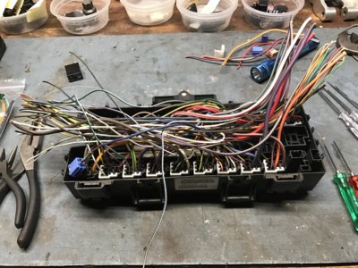
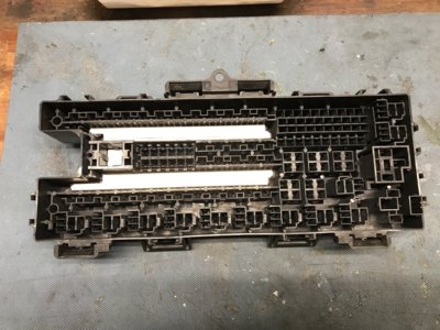
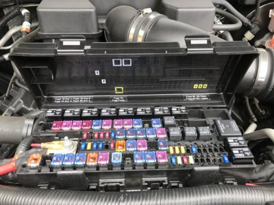
The main power feeds to the maxi-fuses are all supplied via metal bus bars. The fuses then bridge the power over to the wired terminal side and ultimately the load. Everything else is connected to both sides of the fuses with wires and terminals.

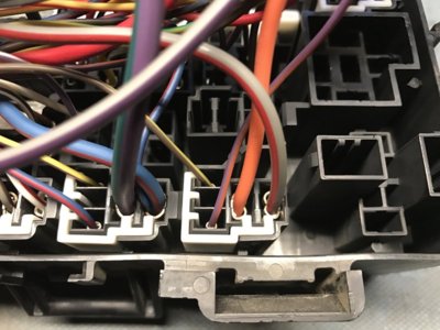
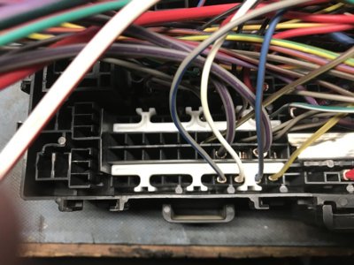
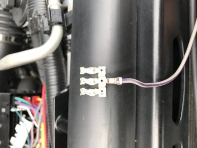
The terminal are all held in with locking tabs in each slot. There are also these white sets of clips that lock those tabs in place to further prevent the possibility of them working their way out. Just getting these out was an exercise in patience.

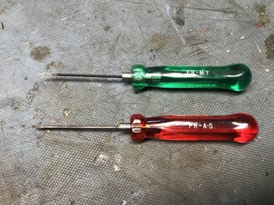
Again, without the proper tools you'll probably just break things and mess up the box. Even with this on the bench and all my tricks it was tough. Ford makes this really a one-way assembly, its not meant to be taken apart. I suspect this is also why they don't sell service terminal ends for the fuse box, at least not that I could find. It's really meant to be replaced as a unit along with the main harness.

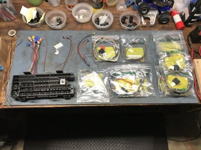
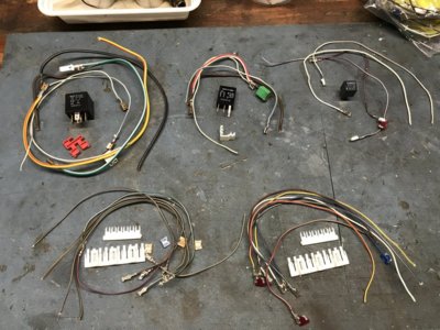
If you go through this process and have the time/energy what you'll end up with is sets of wiring, fuses and relays for all the main components in the fuse box; standard relay, mini relay, micro relay, micro fuse, maxi fuse and a BUNCH of terminals. What you can do then is use any open slot/position in the box to wire in new fused power circuits for your needs. You'll just need a consolidated ground location but that's easy and you won't have relays and fuses all over the engine bay.

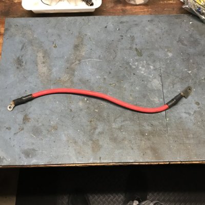
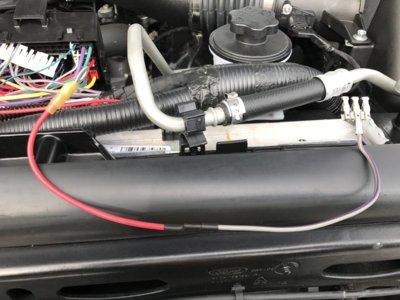
I also got the cool OEM cable that goes from the battery to the fuse box for a later project ;-)

Needless to say I'll never use all of these so if you have the need, contact me and I'll sell you a kit to wire in what you need.
 

Attachments

  • IMG_1865.jpg
    IMG_1865.jpg
    145.4 KB · Views: 43
  • IMG_1866.jpg
    IMG_1866.jpg
    160.1 KB · Views: 47
  • IMG_1867.jpg
    IMG_1867.jpg
    84 KB · Views: 41
OP
OP
andreb

andreb

Full Access Member
Joined
Dec 23, 2014
Posts
183
Reaction score
155
Location
City by the Bay
Now that I had all the parts out I created three new hot fuses locations at the far end of the box. Positions 82-84. I used this 1-into-3 terminal and spliced a short wire and ring terminal onto it. This connects to the main lug/tap. Then just add a fuse and the other terminal runs to the load. I choose a wire gauge for the load side that meets the amperage requirements and the correct fuse as well.

There are also some spare fuse slots in my truck I can use for future projects and only have to add the load side terminal.

low-profile J-Case cartridge fuses
50 – not used
55 – not used
64 – not used
70 – not used
80 – 84 not used

These positions are allocated per the manual but are open/unused in my truck.

9 – Relay - Trailer tow battery charger (future plans)
11 – 30 amp Power running board motors
45 – 10 amp Alt sensor NA
71 – 20 amp Heated rear seats (future plans)
79 – 5 amp Rain Sensor (future plans)

There is also one large, two mini, and one micro relay positions open.

I did this work along with the fuel pump fuse mod. and then labeled things on the lid for reference. While I had the fuse box support out I sanded all the edges smooth and covered it with spray-on Plasti Dip. Looks so much better IMO.
 

Attachments

  • IMG_1412.jpg
    IMG_1412.jpg
    64.8 KB · Views: 43
  • IMG_1411.jpg
    IMG_1411.jpg
    94.9 KB · Views: 35
  • IMG_1844.jpg
    IMG_1844.jpg
    131.6 KB · Views: 53
Top